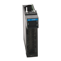
Do you have a question about the Allen-Bradley 1756-IB16 and is the answer not in the manual?
Introduces the Studio 5000 Engineering and Design Environment for programming ControlLogix controllers.
Explains how I/O modules are owned by controllers, and the functions of an owner-controller.
Explains signal propagation delays inherent to modules and user-configurable filter times.
Explains how controllers obtain input status via multicast data upon change of state or requested packet interval.
Explains how owner-controllers send output data to modules at task end or RPI, and the concept of output data echo.
Explains how digital input modules interface with sensing devices and convert signals to logic levels.
Discusses how output modules drive various output devices and guidelines for system design.
Lists features common to all ControlLogix digital I/O modules, including RIUP and module fault reporting.
Describes how electronic keying prevents communication to modules that don't match type and revision expectations.
Details how to suspend a connection between an owner-controller and an I/O module for maintenance or upgrades.
Explains using Coordinated System Time (CST) for timestamping inputs and scheduling outputs.
Describes using CIP Sync for precise real-time synchronization of controllers and devices.
Describes internal electronic or mechanical fusing that protects output modules from overcurrent damage.
Describes the feature allowing modules to turn outputs On or Off at a scheduled time.
Discusses factors to consider when designing systems with diagnostic input modules.
Explains that diagnostic output modules drive digital inputs and may require a shunt resistor for leakage current.
Details how diagnostic I/O modules latch faults, even if the error condition clears, and how to enable/disable it.
Explains how diagnostic I/O modules timestamp faults or clears using the ControlLogix system clock.
Describes how diagnostic I/O modules set bits to indicate faults on a point-by-point basis.
Details the feature used to verify field wiring connection by checking for minimum leakage current.
Describes the feature on output modules that detects loss of field power and sends a point-level fault.
Explains how no load detection senses the absence of field wiring or a missing load from output points.
Informs about logic-side instructions being accurately represented on the power side of a switching device.
Provides instructions for installing or removing ControlLogix I/O modules while chassis power is applied (RIUP).
| Product Type | Digital Input Module |
|---|---|
| Number of Inputs | 16 |
| Input Voltage | 24V DC |
| Category | Control Unit |
| Input Voltage Range | 10-30V DC |
| Input Current | 7 mA |
| Input Delay | 1 ms |
| Backplane Current @ 24V DC | 0.1 A |
| Isolation Voltage | 50V DC continuous, Basic Insulation Type, tested at 1500V DC for 60 s |
| Operating Temperature | 0 to 60 °C |
| Storage Temperature | -40 to 85 °C |
| Relative Humidity | 5 to 95% non-condensing |
| Module Location | Chassis |
| Module Width | 1.5 in |
| Compatibility | ControlLogix |


 Loading...