Rockwell Automation Publication 1756-UM013B-EN-P - October 2019 21
Digital Safety I/O Module Operation in a Control System Chapter 1
About the Modules
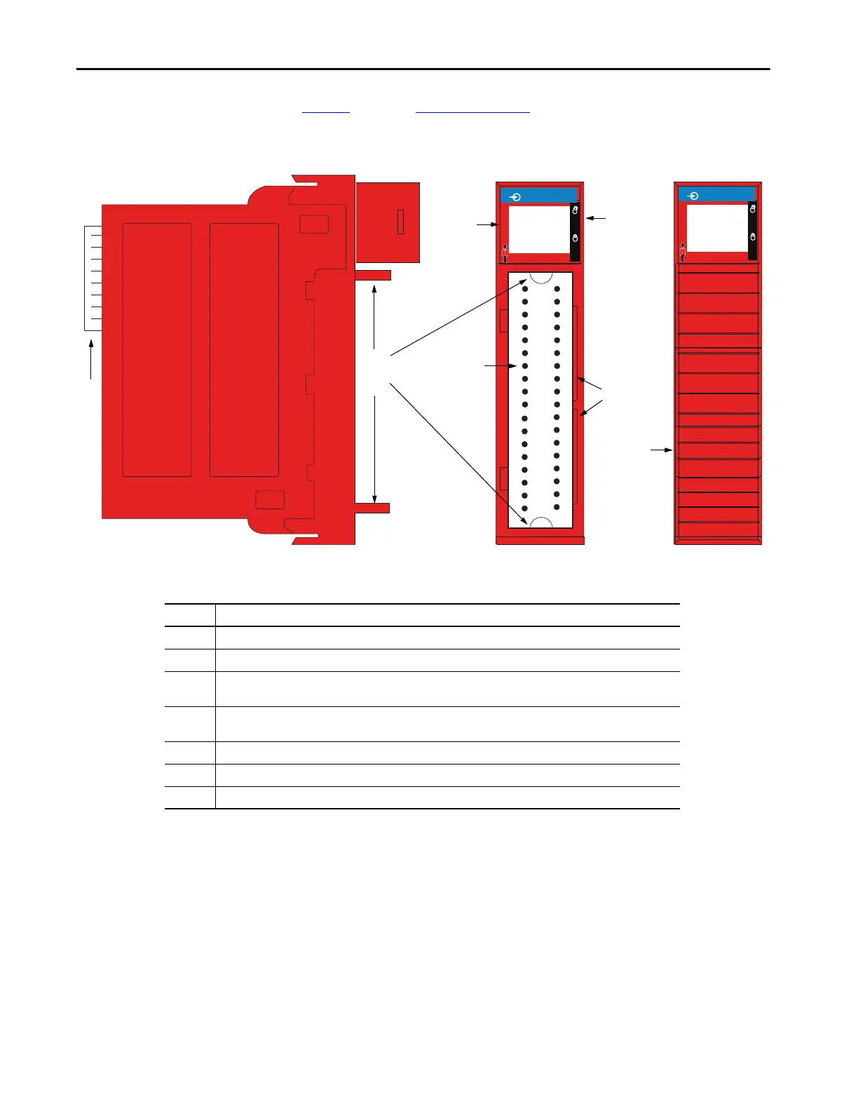
Figure 2 below and Figure 3 on page 22 show the parts of a 1756 ControlLogix
digital safety I/O modules.
Figure 2 - Example 1756-IB18S Module
SAFETY
FLT
ST
0 1 2 3 4 5 6 7
0 1 2 3 4 5 6 7
O
K
DC INPUT
FLT
ST
8 9 10 11 12 13 14 15
8 9 10 11 12 13 14 15
SAFETY
FLT
ST
0 1 2 3 4 5 6 7
0 1 2 3 4 5 6 7
O
K
DC INPUT
FLT
ST
8 9 10 11 12 13 14 15
8 9 10 11 12 13 14 15
Item Description
1 Backplane Connector—Interface for the ControlLogix system that connects the module to the backplane.
2 Top and bottom guides—Guides provide assistance in seating the RTB onto the module.
3 Status indicators—Indicators display the status of communication, module health, and input/output devices.
Indicators help in troubleshooting anomalies.
4 Connector pins—Input/output, power, and grounding connections are made to the module through these pins with
the use of an RTB.
5 Locking tab—The locking tab anchors the RTB on the module, maintaining wiring connections.
6 Slots for keying—Mechanically keys the RTB to help prevent making the wrong wire connections to your module.
7 Module with RTB installed

 Loading...


