EasyManua.ls Logo

Allen-Bradley 22A-D8P7N104 - User Manual

Allen-Bradley 22A-D8P7N104
12 pages
To Next Page IconTo Next Page
Loading...
Quick Start
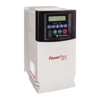
PowerFlex 4 Adjustable
Frequency AC Drive
FRN 2.xx
This Quick Start guide summarizes the basic steps needed to install,
start-up and program the PowerFlex 4 Adjustable Frequency AC Drive.
The information provided Does Not
replace the User Manual and is
intended for qualified drive service personnel only.
For detailed PowerFlex 4 information including EMC instructions,
application considerations and related precautions refer to the
PowerFlex 4
User Manual
, Publication 22A-UM001x on the CD
supplied with the drive or at
www.ab.com/manuals/dr.
General Precautions
!
ATTENTION:
The drive contains high voltage capacitors which take
time to discharge after removal of mains supply. Before working on
drive, ensure isolation of mains supply from line inputs [R, S, T (L1,
L2, L3)]. Wait three minutes for capacitors to discharge to safe voltage
levels. Failure to do so may result in personal injury or death.
Darkened display LEDs is not an indication that capacitors have
discharged to safe voltage levels.
!
ATTENTION:
Equipment damage and/or personal injury may result
if this parameter (A092 [Auto Rstrt Tries], A094 [Start At PowerUp]) is
used in an inappropriate application. Do not use this function without
considering applicable local, national and international codes,
standards, regulations or industry guidelines.
!
ATTENTION:
Only qualified personnel familiar with adjustable
frequency AC drives and associated machinery should plan or
implement the installation, start-up and subsequent maintenance of the
system. Failure to comply may result in personal injury and/or
equipment damage.
!
ATTENTION:
This drive contains ESD (Electrostatic Discharge)
sensitive parts and assemblies. Static control precautions are required
when installing, testing, servicing or repairing this assembly.
Component damage may result if ESD control procedures are not
followed. If you are not familiar with static control procedures,
reference A-B publication 8000-4.5.2, “Guarding Against Electrostatic
Damage” or any other applicable ESD protection handbook.
!
ATTENTION:
An incorrectly applied or installed drive can result in
component damage or a reduction in product life. Wiring or application
errors, such as, undersizing the motor, incorrect or inadequate AC
supply, or excessive ambient temperatures may result in malfunction of
the system.
Allen-Bradley Drives
Question and Answer IconNeed help?

Do you have a question about the Allen-Bradley 22A-D8P7N104 and is the answer not in the manual?

Allen-Bradley 22A-D8P7N104 Specifications

General IconGeneral
Model22A-D8P7N104
I/O TypeDigital
Output TypeRelay
Communication PortsEtherNet/IP
Protocol SupportEtherNet/IP
Operating Temperature0 to 40 °C
Storage Temperature-40 to 85 °C
Relative Humidity5 to 95% noncondensing
CertificationsCE
Enclosure TypeIP20
BrakingDynamic Braking
Control MethodSensorless Vector Control, Volts per Hertz

Summary

General Precautions

High Voltage Capacitor Discharge Warning

Warning about high voltage capacitors and required discharge time before working on the drive.

Parameter Usage Precautions

Caution on inappropriate use of Auto Restart and Start at PowerUp parameters.

Qualified Personnel Requirement

Emphasizes that only qualified personnel familiar with drives should perform installation and maintenance.

ESD Sensitive Parts

Notes that the drive contains ESD sensitive parts and requires static control precautions.

Incorrect Application or Installation Warnings

Warns about potential damage or reduced life from incorrect wiring or application errors.

General Grounding Requirements

Power Wiring

Control Terminal Block

Prepare For Drive Start-Up

Start-Up Safety Precautions

Critical warnings regarding live voltages and the need for qualified personnel.

Pre-Power Application Checks

Steps to confirm input connections, AC line power, digital control power, and DIP switch settings.

Applying Power and Initial Familiarization

Instructions for applying AC power and becoming familiar with keypad features.

Start, Stop, Direction, and Speed Control

Overview of default keypad control and disabling reverse operation.

Integral Keypad Operations

Viewing and Editing Parameters

Viewing and Editing Parameter Values

Process for selecting, viewing, entering edit mode, and changing parameter values.

Basic Program Group Parameters

Fault Codes and Troubleshooting

F2 Auxiliary Input Fault

Indicates a fault related to auxiliary input wiring.

F4 UnderVoltage Fault

Occurs when incoming AC line voltage is too low.

F5 OverVoltage Fault

Occurs due to high line voltage or regeneration.

F6 Motor Stalled Fault

Indicates the motor is stalled or current limit is too low.

F7 Motor Overload Fault

Triggered by excessive motor load or current.

F8 Heatsink OvrTmp Fault

Indicates the drive's heatsink temperature is too high.

F12 HW OverCurrent Fault

Hardware-detected overcurrent condition.

F13 Ground Fault

Detects a ground fault in the motor or wiring.

Related product manuals