Rockwell Automation Publication 2711P-TD001D-EN-P - February 2011
6 Wiring and Grounding Guidelines for PanelView Plus Terminals
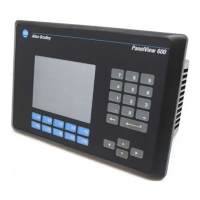
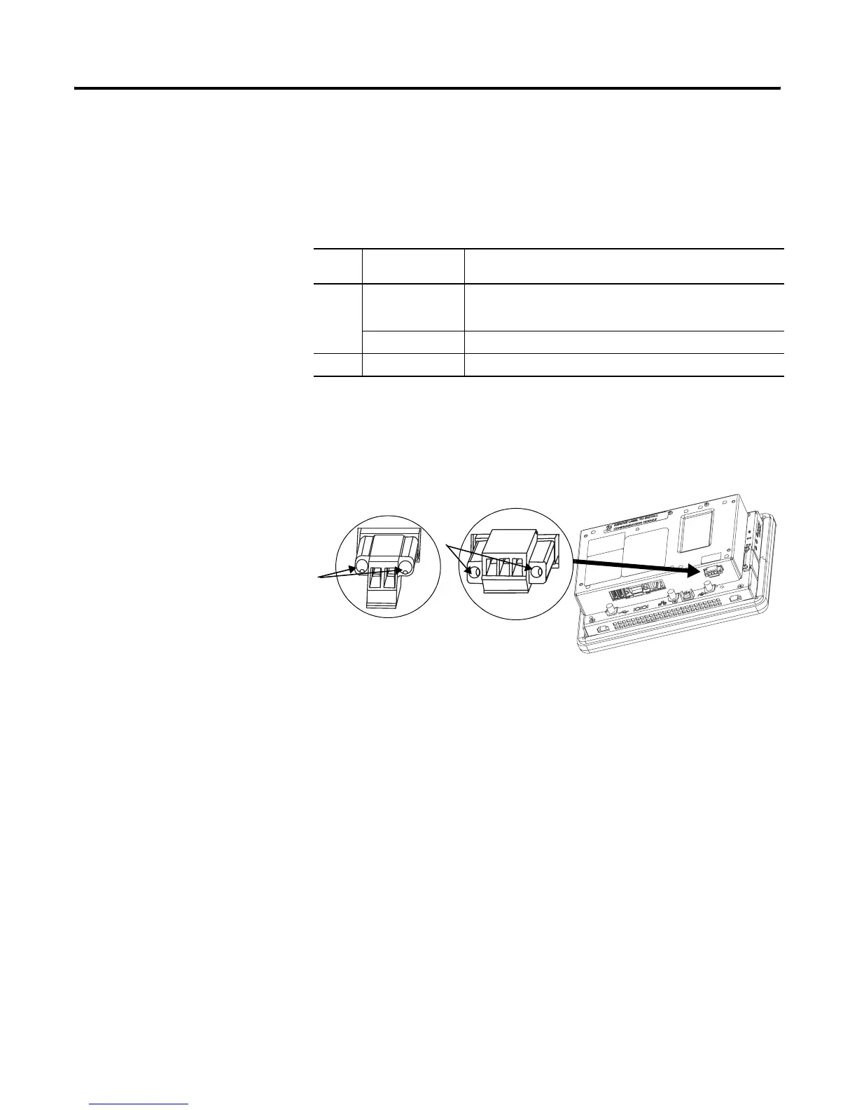
PanelView Plus 700 to 1500 Terminals
The terminal block installed in the 700 to 1500 terminals depends on the series
of the logic module and the power input type.
Follow these steps to remove the terminal block.
1. Loosen the two screws that secure the terminal block.
2. Gently pull the terminal block away from the connector.
Follow these steps to install the terminal block.
1. Reattach the terminal block to the connector until seated.
2. Tighten the two screws that secure the terminal block to the connector.
Table 1 - Power Terminal Block
Power
Input
This Terminal
Block is Used
With This Device
DC 2-position • Series A or later PanelView Plus 6 logic modules
• Series E or later PanelView Plus logic modules
(1)
• PanelView Plus Compact 1000 terminals
(1) These logic modules support FactoryTalk View Machine Edition software, version 5.1 or earlier.
3-position • Series A-D logic modules (PanelView Plus)
(1)
AC 3-position • All terminals and logic modules with an AC power input
3-position AC or DC
2-position DC Terminal
 Loading...