Visit our website: www.ab.com/catalogs
Bulletin 900-TC
Single-Loop Temperature/Process Controller
17
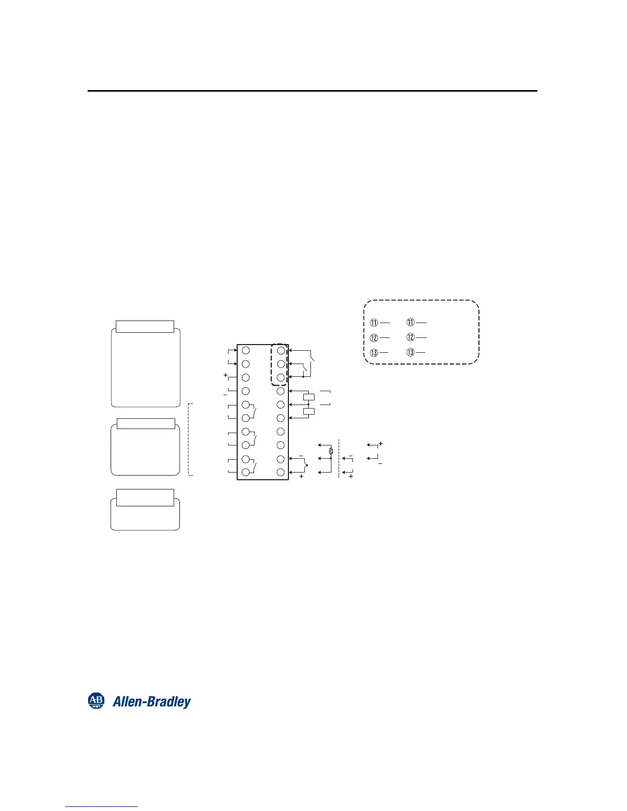
Wiring Terminals
Bulletin 900-TC8 — Wiring Terminals
Bulletins 900-TC8 and 900-TC16
Wiring Terminals — General Guidelines
Note: Input power supply available: 100…240 V AC, or 24 V AC/DC
y The voltage output (SSR control output) is not electrically isolated from the controller’s internal circuits. When using a grounded
thermocouple, do not connect the control output terminals to earth ground. If the control output terminals are connected to earth ground,
errors will occur in the measured temperature values as a result of ground loop leakage current.
y Standard insulation ratings exist between any of the following: power supply terminals, input terminals, output terminals, and
communication terminals. If reinforced insulation is required, provide additional insulation, such as spatial distance or material insulation, as
defined by IEC 60664.
y Separate input leads and power lines to protect the Bulletin 900-TC8/900-TC16 and its lines from external noise.
y Solderless lugs are recommended when wiring to the Bulletin 900-TC8/900-TC16 wire terminals. However, if lugs are not used, the
controller’s screw terminals will accept two solid or stranded wires (no mixing) 14…24 AWG.
y Tighten the terminal screws using a torque 1.13…1.36 N•m (10…12 lb-in).
y Use the following type of solderless lugs for M3.5 screws.
 Loading...