Visit our website: www.ab.com/catalogs
Bulletin 900-TC
Digital Temperature Controller
21
Installation, Continued
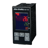
Bulletin 900-TC32
Panel Mounting
1. Insert the Bulletin 900-TC32 into the mounting hole in the panel
from the front. Ensure the waterproof gasket is in place if this is a
IP66 UL Type 4X enclosure.
2. Push the panel mounting adapter along the Bulletin 900-TC32
body from the rear terminals up to the panel, and secure it
temporarily.
3. Tighten the two screws on the adapter. When tightening the two
screws, tighten them alternately, keeping the torque to within
approximately 0.29…0.39 N•m (2.57…3.45 lb•in).
Removing and Attaching the Wiring Terminal Cover Plate
A damaged Bulletin 900-TC32 can quickly be replaced by removing
the field terminal plate.
1. Press in firmly on the fasteners at both sides of the terminals to
unlock the terminal plate and pull it upwards.
2. Remove the terminal plate with the field wires attached.
3. Before you replace/insert the terminal plate on the replacement
Bulletin 900-TC32, make sure that the pins match the positions of
the holes in the terminal plate, and press it into place on the
controller.
Wiring Precautions
Bulletin 900-TC32
Connect the terminals as specified below.
Terminal No. Cables Pin Terminals
1…6 AWG 24…14 2.1 mm dia. max.
7…9 AWG 28…22 1.3 mm dia. max.
The exposed current-carrying part to be inserted into terminals must
be 5…6 mm.
Tighten the terminal screws to the torque specified below.
Terminal No. Screw Maximum Tightening Torque
1…6 M2.6 0.23…0.25 N•m (2.04…2.21 lb•in)
7…9 M2 0.12…0.14 N•m (1.06…1.24 lb•in)
 Loading...