EasyManua.ls Logo

Allen-Bradley Pico 1760-L12BWB-NC User Manual

Allen-Bradley Pico 1760-L12BWB-NC
18 pages
To Next Page IconTo Next Page
Page #1 background imageLoading...
Page #1 background image
Artisan Technology Group is your source for quality
new and certied-used/pre-owned equipment
FAST SHIPPING AND
DELIVERY
TENS OF THOUSANDS OF
IN-STOCK ITEMS
EQUIPMENT DEMOS
HUNDREDS OF
MANUFACTURERS
SUPPORTED
LEASING/MONTHLY
RENTALS
ITAR CERTIFIED
SECURE ASSET SOLUTIONS
SERVICE CENTER REPAIRS
Experienced engineers and technicians on staff
at our full-service, in-house repair center
WE BUY USED EQUIPMENT
Sell your excess, underutilized, and idle used equipment
We also offer credit for buy-backs and trade-ins
www.artisantg.com/WeBuyEquipment
REMOTE INSPECTION
Remotely inspect equipment before purchasing with
our interactive website at www.instraview.com
LOOKING FOR MORE INFORMATION?
Visit us on the web at www.artisantg.com for more
information on price quotations, drivers, technical
specications, manuals, and documentation
Contact us: (888) 88-SOURCE | sales@artisantg.com | www.artisantg.com
SM
View
Instra
Question and Answer IconNeed help?

Do you have a question about the Allen-Bradley Pico 1760-L12BWB-NC and is the answer not in the manual?

Allen-Bradley Pico 1760-L12BWB-NC Specifications

General IconGeneral
ManufacturerAllen-Bradley
SeriesPico
Part Number1760-L12BWB-NC
Input Voltage24 VDC
Number of Inputs8
Number of Outputs4
Output TypeRelay
Communication PortRS-232
Programming LanguageLadder Logic
MountingDIN Rail
Input Frequency50/60 Hz
Programming SoftwarePicoSoft
Weight0.5 kg
Product TypeProgrammable Controller
Operating Temperature0°C to 55°C
Relative Humidity5 to 95% (non-condensing)

Summary

Installation Instructions

Pico Controller Overview

Introduces the specific Pico controller model and its catalog numbers.

Electrical Shock Hazard Warning

Critical safety notice about electrical hazards during installation for qualified personnel only.

Controller Components and Wiring

Front View and Component Identification

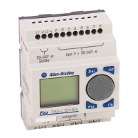
Details the front panel layout and identifies components.

Component Functionality Descriptions

Explains the function of each numbered component on the controller's front panel.

Input Connection Diagrams

Provides standard wiring diagrams and specifications for input terminals across models.

Output Terminals and Specifications

Details output terminal configurations and electrical specifications.

Operation and Configuration

Commissioning Language Selection

Guide for selecting the user interface language during initial setup.

Internal Logic Elements Mapping

Explains mapping of internal logic elements to terminal assignments.

Operating Temperature and Retention Settings

Covers operating temperature range, display legibility, and retention settings.

Operational Modes and Menu Changes

Details RUN/STOP modes, menu navigation, and parameter modifications.

Accessories and Installation

Accessory Installation and Safety

Guides on installing accessories like memory cards and PC cables, including safety precautions.

Physical Mounting and Fitting

Instructions on physically attaching the controller to DIN rails or mounting plates.

Controller Dimensions and Documentation

Presents controller dimensions and lists related product documentation.

Safety Certification

Hazardous Location Certification

Details CSA certification for hazardous locations and associated safety warnings.

Explosion Hazard Safety Warning

Critical warning about explosion risks and procedures for safe operation in hazardous environments.

Related product manuals