Rockwell Automation Publication 750-IN001O-EN-P - October 2014 227
I/O Wiring Chapter 5
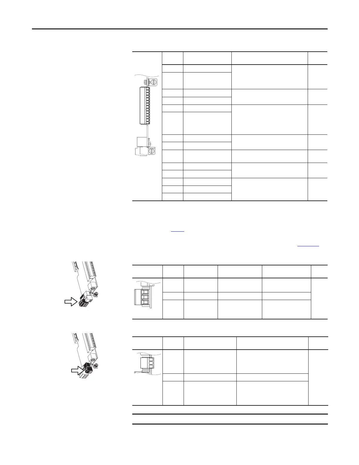
Table 38 - TB1 Terminal Designations
Note: 753 Main Control Board I/O TB1 wiring examples begin on page 241.
Table 39 - TB2 Terminal Designations
Table 40 - TB3 Terminal Designations
Terminal Name Description Related
Param
Ao0– Analog Out 0 (–) Bipolar, ±10V
(1)
, 11 bit & sign, 2 k ohm
minimum load.
4-20 mA
(1)
, 11 bit & sign, 400 ohm maximum
load.
(1) Mode is selected by parameter only.
270
Ao0+ Analog Out 0 (+)
10VC 10 Volt Common For (+) 10 Volt references.
2k ohm minimum.
+10V +10 Volt Reference
Ai0– Analog Input 0 (–) Isolated
(2)
, bipolar, differential, 11 bit & sign.
Voltage Mode:
(3)
±10V @ 88k ohm input
impedance.
Current Mode:
(3)
0-20 mA @ 93 ohm input
impedance
(2) Differential Isolation - External source must be maintained at less than 160V with respect to PE. Input provides high common mode
immunity.
(3) Mode is selected by jumper J4.
255
Ai0+ Analog Input 0 (+)
Ptc– Motor PTC (–) Motor protection device
(Positive Temperature Coefficient).
(4)
(4) See HW Input PTC on page 242 for PTC data.
250
Ptc+ Motor PTC (+)
T0 Transistor Output 0 Open drain output, 48V DC, 250 mA
maximum load.
24VC 24 Volt Common Drive supplied logic input power.
150 mA maximum
+24V +24 Volt DC
Di C Digital Input Common 24V DC (30V DC Max.) - Opto isolated
High State: 20…24V DC
Low State: 0…5V DC
220
Di 1 Digital Input 1
Di 2 Digital Input 2
Ao0-
Ao0+
10VC
+10V
Ai0-
Ai0+
Ptc-
Ptc+
To0
24VC
+24V
Di C
Di 1
Di 2
Fixed I/O Terminal Name Description Rating Related
Param
R0NC Relay 0 N.C. Output Relay 0 normally
closed contact.
240V AC, 24V DC, 2 A max.
Resistive Only
285
286
291
292
R0C Relay 0 Common Output Relay 0 common
R0NO Relay 0 N.O. Output Relay 0 normally
open contact.
240V AC, 24V DC, 2 A max.
General Purpose (Inductive)
/ Resistive
R0NC
R0C
R0NO
Power Block Terminal Name Description Related
Param
Di 0dc Digital Input 0
24V DC (30V DC Max.)
Connections for Digital Input 0 when signal
is DC power.
High State: 20…24V DC
Low State: 0…5V DC
220
Di C Digital Input Common Digital input common
Di 0ac Digital Input 0
120V AC (132V AC Max.)
Connections for Digital Input 0 when signal
is AC power.
High State: 100…132V AC
Low State: 0…30V AC
This terminal becomes a hardware enable when the ENABLE jumper is removed.

 Loading...


