50 Rockwell Automation Publication 750-IN001O-EN-P - October 2014
Chapter 3 Lift and Mount the Drive
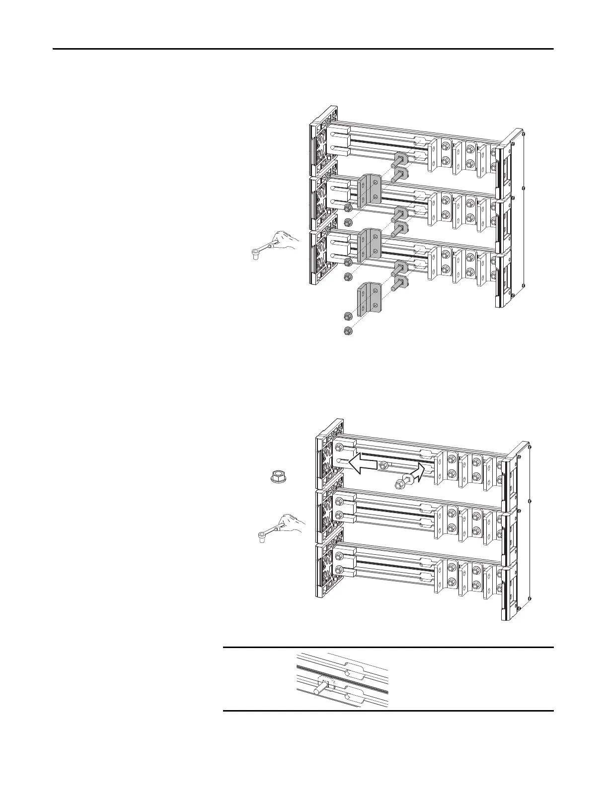
14. Remove the left most L-bracket from each of the six wiring bay bus bars to
access the channel notches.
15. Insert the 12 carriage bolt assemblies ➊ into the 12 wiring bay bus bar
channels.
16. Slide the carriage bolt assemblies ➋ into the bus bar couplers on the left
and tighten.
Verify that clamp fits squarely in the bus bar
channel.
17 mm
M10 x 1.5
38.0 N•m (336 lb•in)
17 mm
➋
➊

 Loading...


