36 Rockwell Automation Publication 750-IN100B-EN-P - July 2017
Chapter 3 Prepare for Installation
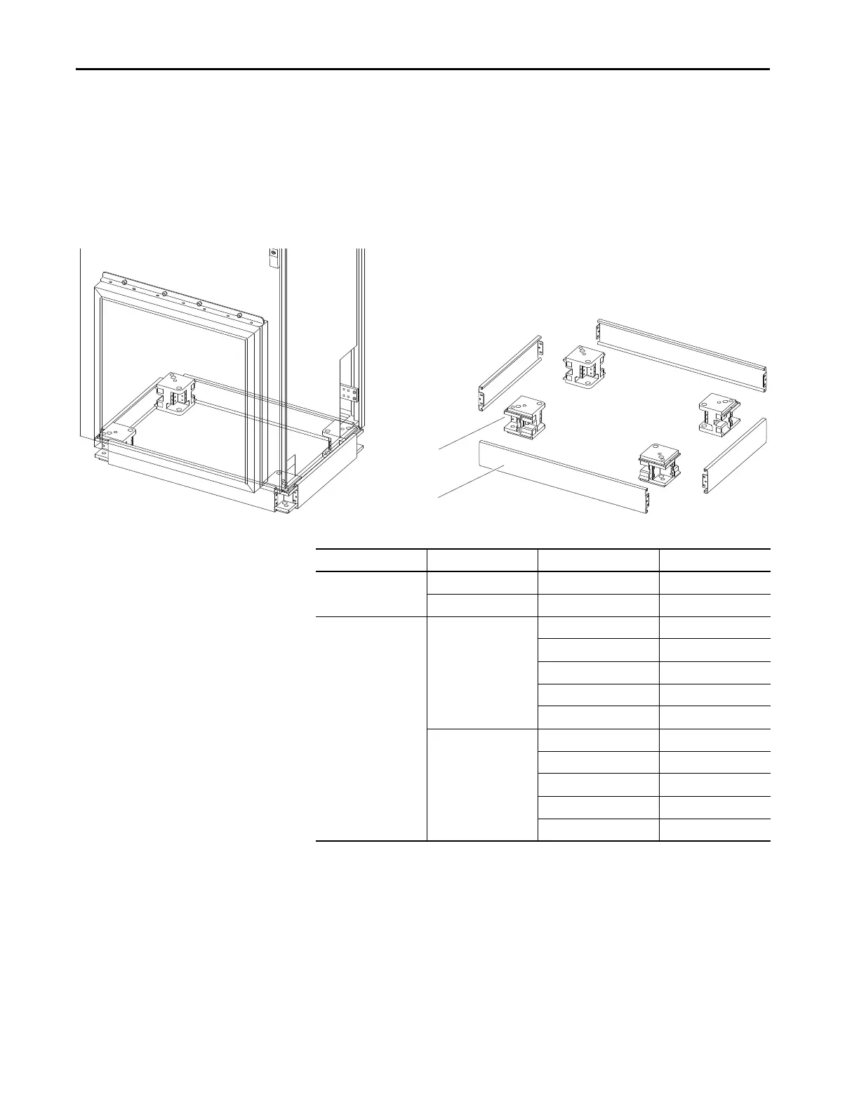
Rittal Corner Base/Plinth System
Rittal Flex-Block base/plinth systems are available from Rittal Corporation in
100 mm (4.0 in.) and 200 mm (8.0 in.) heights. Systems provide a base/plinth
for each corner of a Rittal TS 8 enclosure and are secured by using an M12
screw in each corner. Follow the manufacturer’s installation instructions.
Figure 11 - Rittal Corner Base/Plinth Mounting
Table 5 - Rittal Flex-Block Base/Plinth System Components
Component Name Height mm (in.) Width and Depth mm (in.) Rittal Model No.
Corner pieces 100 (4.0) N/A 8100.000
200 (8.0) N/A 8200.000
Trim panels (optional) 100 (4.0) 300 (11.8) 8100.300
400 (15.7) 8100.400
600 (23.6) 8100.600
800 (31.5) 8100.800
1000 (39.4) 8100.010
200 (8.0) 300 (11.8) 8200.300
400 (15.7) 8200.400
600 (23.6) 8200.600
800 (31.5) 8200.800
1000 (39.4) 8200.010

 Loading...


