PowerFlex 755 On-Machine Packaged Drive 5
Rockwell Automation Publication 750-PC004B-EN-P - April 2019
Mount the Packaged Drive
For more information on environmental requirements, see Enclosure Specifications on page 2. Dimensions are
shown in millimeters and (inches). For more information on mounting the packaged drive, see PowerFlex 755
On-Machine Packaged Drive User Manual, publication 750-UM006
.
Minimum Mounting Clearances
Be sure that there is adequate clearance for air circulation around the packaged drive. For best air movement, do
not mount packaged drives directly above each other. No devices are to be mounted behind the packaged drive.
This area must be kept clear of all control and power wiring.
On-Machine Packaged Drive Connections
This section explains the different gland plate configurations and what the abbreviations represent on the gland
plate. The cables for this unit are supplied by the user but must be mated with the proper connector. For more
information on connectors and cables, see PowerFlex 755 On-Machine Packaged Drive Technical Data,
publication 750-TD003
.
All connections needed to setup the packaged drive, including the EtherNet/IP network connection, are made
without removing the front cover. The cover does not need to be removed to bring a packaged drive into service.
Connecting Connectors
This section goes into detail about the design of the connectors and advises installers about having the
appropriate connector for the assigned receptacle.
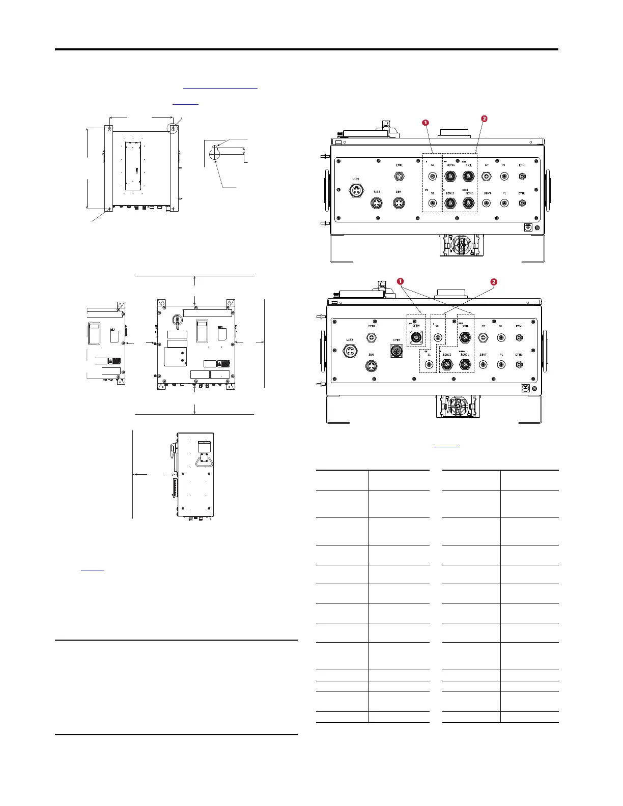
Factory-installed Gland Plate
The On-Machine Packaged Drive has a highly configurable gland plate, two of the gland plates that are offered
are shown in this section.
The call outs 1 and 2 indicate areas of the gland plate that vary with the different types of safety modules and
encoder options that are chosen. For more information on other available configurations, see PowerFlex 755
On-Machine Packaged Drive User Manual, publication 750-UM006
.
IMPORTANT Many of the connectors could appear to be interchangeable because they have the same
mounting hole pattern. Verify your pin out and connectors before attaching to the
On-Machine Packaged Drive. Review connectors carefully.
The connector groups that follow have similar mounting hole patterns and are
interchangeable:
• Encoder CFBM and Power Connector CPBM
• Encoders ENC0, HIPSC, SSIL, DENC0, DENC1, and SSISC
• Power Connectors: L123, T123, DBR, and EMB1
• Control Power Connectors: CP, CPBR, and EMB2
• Safety Connectors: S0 and S1
• Control Power Connector: P0, P1, and DBRT
527.0
[20.75]
See detail A
673.1
[26.50]
ø12.00
[0.47]
15.00
[0.59]
ø 24.00
[0.94]
Detail A 2X
ø 5.28
[0.207] 2X
152.4
(6.00)
152.4
(6.00)
152.4
(6.00)
152.4
(6.00)
914.4
(36.00)
Drive or
other device
Dimensions are in millimeters and (inches).
Right View
On-Machine Packaged Drive Gland Plate Abbreviation Definitions
Termi na l
Designations
Description Terminal
Designations
Description
L123 Input Power CFBM Allen-Bradley® Servo
Bulk Head Hiperface
Encoder
T123 Output Power CPBM Allen-Bradley Servo
Motor Power and
Brake
DRB Dynamic Brake ENCO M23 Incremental
Encoder
EMB1 380V…480V AC Source
Mechanical Brake
HIPSC M23 Hiperface SC
Encoder
EMB2 24V DC Mechanical
Brake
SSIL M23 SSI Linear Encoder
CP 24V DC Control Power DENCO M23 Dual Incremental
Encoder - 0
CPBR 24V DC Brake Power DENC1 M23 Dual Incremental
Encoder - 1
DBRT Brake Resistor
Thermostat
Temp er at ure
SSISC M23 SSI SC Rotary
Encoder
SO S0 Network Safety (S3) PO P0 Digital Input
S0 S0 Network Safety (S4) P1 P1 Digital Input
S0 S0 Network Safety
(S4 with brake)
ETH1 EtherNet/IP Link 1
S1 S1 Network Safety (S4) ETH 2 EtherNet/IP Link 2
Maximum Possible Connector Details: Induction Motor with Source Brake
Maximum Possible Connector Details: Servo Motor with 24V DC Brake

 Loading...


