Publication 2711-UM014B-EN-P
12-26 Terminal Connections
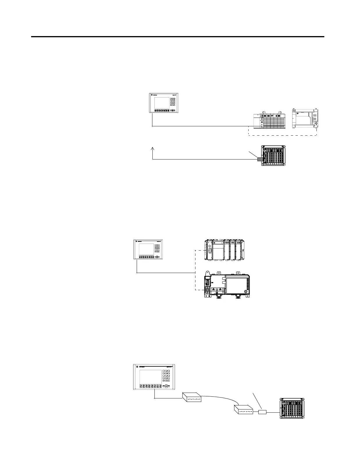
Connecting to an SLC, PLC or MicroLogix 1500LRP
The following shows a point-to-point connection between the DF1
port of the PanelView and an SLC or PLC controller.
Use an optical isolator or equivalent when grounding level differences
exist between the controller or modem and the PanelView.
Connecting to a CompactLogix or FlexLogix
The following shows a point-to-point connection between the DF1
port of the PanelView and a CompactLogix or FlexLogix controller.
Using a Modem
Wire or radio modem communications is possible between a DF1
terminal and controller. Each modem must support full duplex
communications. Refer to your modem user manual for details on
settings and configuration.
PanelView
DF1 Port
SLC 5/03, 5/04, 5/05
PLC 5
DF1 Port
2711-NC13, -NC14 Cable
2711-NC13, -NC14 Cable
9 to 25-Pin
Adapter
DF1 Port
MicroLogix
1500LRP
DF1 Port
DF1 Port
2711-NC13, -NC14 Cable
CompactLogix
PanelView
FlexLogix
DF1 Port
PanelView
Modem
DF1 Port
Modem
Controller
Optical Isolator
 Loading...