Publication 2711-UM014B-EN-P
2-2 Applying Power and Resetting Terminal
Connecting AC Power
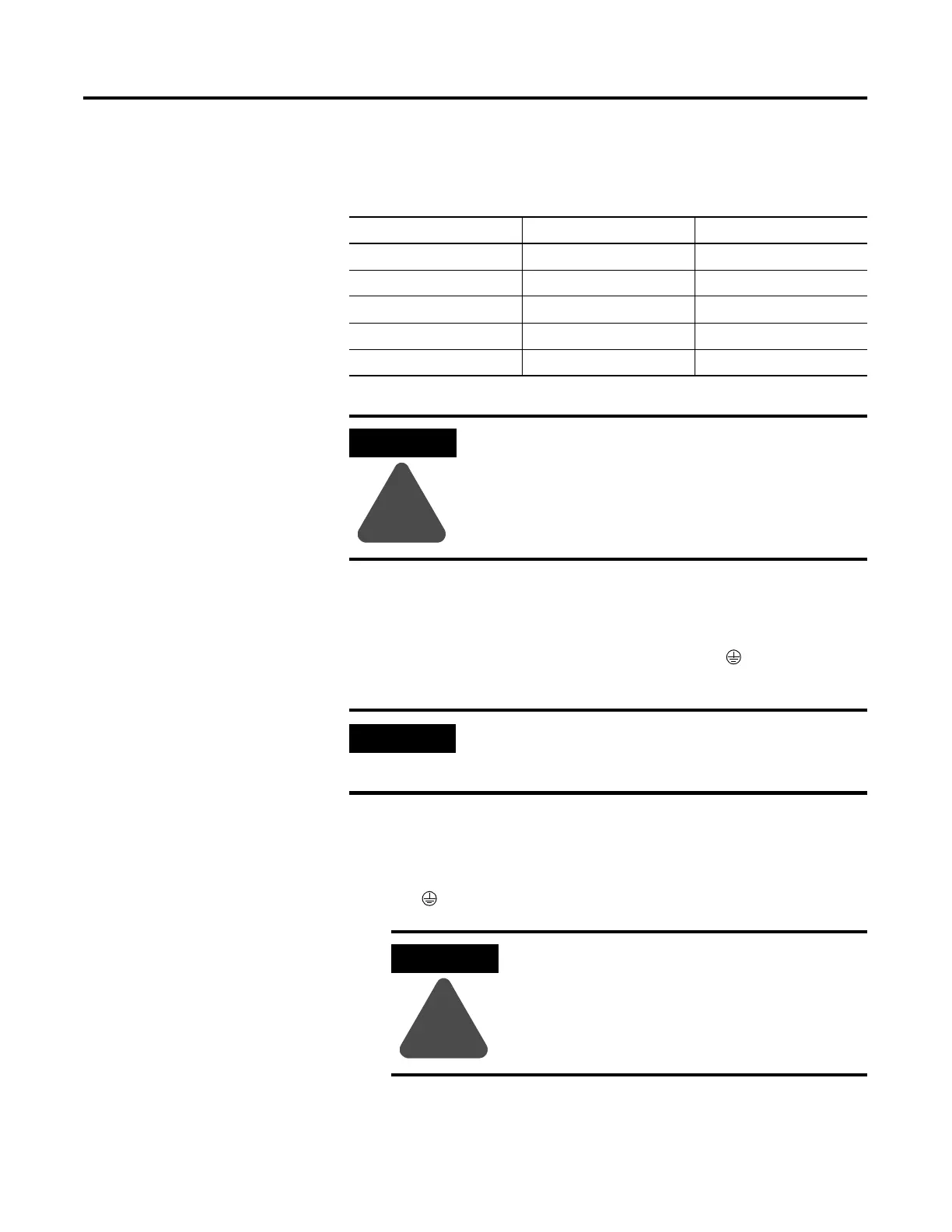
Below are AC electrical ratings for the PanelView terminals. The
PV550/PV600 touch screen only terminal is available only with DC
power, not AC power.
AC Power Connections
The PanelView terminals are IEC 1131-2 Equipment Class I devices
and require you to connect the GND (Ground) or (Protective
Earth) terminal to an earth conductor.
To connect power to the AC versions of the PanelView:
1. Secure AC power wires to the L1 and L2N terminal block screws.
2. Secure the Earth Ground/Protective Earth wire to the GND or
the screw on the terminal block.
3. Apply power to the terminal.
Terminal Type Supply Voltage Power Consumption
PV550 85 to 264V ac, 47 to 63 Hz 45 VA maximum
PV600 85 to 264V ac, 43 to 63 Hz 60 VA maximum
PV900M/PV900C 85 to 264V ac, 47 to 63 Hz 110 VA maximum
PV1000G/PV1000C 85 to 264V ac, 47 to 63 Hz 100 VA maximum
PV1400 85 to 264V ac, 43 to 63 Hz 200 VA maximum
ATTENTION
!
Do not apply power to the PanelView terminal until
all wiring connections have been made. Failure to do
so may result in electrical shock.
IMPORTANT
The PanelView terminals are designed for safe use
when installed in a NEMA Type 12, 13, 4X (indoor
use only), IP54 or IP65 rated enclosure.
ATTENTION
!
Improper wiring of the power terminals may
result in voltage at the communication
connector shells. Refer to the figure below
when wiring.
 Loading...