Do you have a question about the Allen-Bradley TLS-GD2 and is the answer not in the manual?
Guidance on proper installation by competent personnel and adherence to specifications.
Important warnings about potential injury, death, or damage from improper use or tampering.
Routine weekly checks for correct operation, signs of abuse, and damage to the switch casing.
Periodic checks including power isolation, terminal tightness, and component wear inspection.
Instructions stating that units should be replaced, not repaired, and not dismantled.
Information regarding UL508 standards, including temperature ratings and conductor/conduit requirements.
Details on the number and type of safety contacts (N.C.) and their direct opening action.
Specifications for the auxiliary contacts (N.O.) including minimum force and type.
The rated impulse withstand voltage (UIMP) for the safety switches.
The minimum current rating for the safety switches.
The maximum speed at which the actuator can operate.
The Ingress Protection (IP) rating indicating resistance to dust and water.
The specified range of ambient temperatures for operation.
The expected mechanical lifespan in operations.
Maximum torque values for fixing bolts, lid screws, and terminal screws.
Description of the locking mechanism type, e.g., Power to Release or Power to Lock.
The voltage and type (AC/DC) of power supply required for the unit.
The pollution degree rating for the electrical environment.
Information on compliance with ISO 14119, the harmonized standard for interlocking devices.
Defines the different types of interlocking devices and their corresponding ISO 14119 coding.
Important attention note regarding the replacement of transit plugs with UL Listed plugs.
Clarification that electrical life is load-dependent and operations are not applicable.
Specifies the SELV or PELV 24V DC requirement for certain models.
Detailed specifications including force ratings, switching current/voltage, and contact ratings.
Warnings about the consequences of improper selection or installation on safety systems.
| Category | Switch |
|---|---|
| Type | Tongue Interlock Switch |
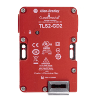
| Series | TLS-GD2 |
| Housing Material | Die-cast Aluminum |
| Protection Rating | IP69K |
| Current Rating | 10 A |
| Standards | EN 60947-5-1 |
| Contact Configuration | 2 N.C. + 1 N.O. |
| Voltage Rating | 600V AC |