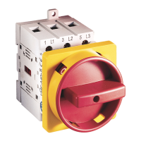
Installation Instructions
4-pole
(Cat. No. 194E)
800E-AW2
2
3
6
5
1
4
7
9
8
Optional
(only for: E, L type)
7
6
5
4
3
1
2
0.7 Nm
[6.2 lb-in]
1.2 Nm
[10.6 lb-in]
PH 2
PH 1
Type HC
Type HE
Mounting position
View
Z
Use front element Cat. No. 194L-HE...
For 40-100 A switches use metal shaft
Metallwellenverbindung für 40-100 A
Pour le montage du 40-100 A utiliser un
arbre metallique
Per sezionatori 40-100 A usare l’albero
metallico
Para el montaje de los 40-100 A utilizar
lo eje metalico
1
0.7 Nm
[6.2 lb-in]
1.2 Nm
[10.6 lb-in]
PH 1
PH 2
2
3
5
4
7
6
Mounting position
View
Z
194E-E...
194E-A...
Use front element Cat. No. 194L-HE...
194L-HC...
194E-HE...
194E-HE...
Load Size [A]
A
(only for
2-holes mounting)
B
(only for
4-holes mounting)
D
16
28
28
25
32
40
63
80
9.5
[3/8]
[1-27/64] or [1-57/64]
[1-27/64] or [1-57/64]
[1-17/64]
[1-17/64]
Load Size [A]
A
(only for
2-holes mounting)
B
(only for
4-holes mounting)
D
16
28
25
32
40
63
80
17
[43/64]
-
[1-27/64] or [1-57/64]
[1-27/64] or [1-57/64]
D
B
B
(A)
ø 3.3
[1/8]
mm
[in]
Z
Attention: To prevent electrical shock, disconnect from power source before installing or servicing. To be commissioned and maintained only by qualified personnel;
pay attention to the operating instructions!
Achtung: Vor Installations- oder Servicearbeiten Stromversorgung unterbrechen, um Unfälle zu vermeiden. Inbetriebsetzung und Wartung nur durch Fachpersonal;
Betriebsanleitung beachten!
Attention: Avant le montage et la mise en service, couper l'alimentation secteur afin d'éviter tout accident. Mise en service et entretien: seulement par du personnel
spécialisé; respecter les instructions d'exploitation!
Attenzione: Per prevenire infortuni, togliere tensione prima dell'installazione o manutenzione. Messa in servizio e manutenzione solo da personale specializzato;
attenersi alle istruzioni per l'esercizio!
Atención: Desconectar la alimentación eléctrica antes de realizar el montaje y la puesta en servico, con el objeto de evitar accidentes. Puesta en servicio y
mantenimiento exclusivamente por personal especializado; respetar las instrucciones de puesta en servicio y mantenimiento!
IEC/EN 60947-3
GB/T 14048.3
UL 60947-4-1
CAN/CSA-C22.2 No. 60947-4-1