EasyManua.ls Logo

Allen-Bradley Stratix 5200 1783-CMS6P - User Manual

Allen-Bradley Stratix 5200 1783-CMS6P
16 pages
To Next Page IconTo Next Page
Loading...
Installation Instructions
Original Instructions
Stratix 5200 Ethernet Managed Switches
Catalog Numbers 1783-CMS6B, 1783-CMS6P, 1783-CMS10B, 1783-CMS10P, 1783-CMS10DP, 1783-CMS10DN, 1783-CMS20DB, 1783-CMS20DP, 1783-CMS20DN
Topic Page
Parts List 5
Required Tools 5
Site Requirements 5
Mount the Switch 6
Ground the Switch 7
Wire the DC Power Source 7
Install the Power Connectors on the Switch 8
Wire External Alarms 9
Connect to Console Ports 11
Install or Remove the SD Card 12
Install or Remove an SFP Module 12
Connect to 10/100 and 10/100/1000 Ports 13
Connect to 10Base-T, 100Base-TX, or 1000Base-T Ports 14
Connect to SFP Module Ports 13
Connect to a Dual-purpose Port 13
Confirm Installation 14
Remove the Switch from the DIN Rail 14
Specifications 15
Additional Resources 15
Question and Answer IconNeed help?

Do you have a question about the Allen-Bradley Stratix 5200 1783-CMS6P and is the answer not in the manual?

Allen-Bradley Stratix 5200 1783-CMS6P Specifications

General IconGeneral
Product TypeManaged Ethernet Switch
Mounting TypeDIN Rail
Power over Ethernet (PoE)Yes
Total PoE Budget60W
Switching Capacity12 Gbps
MAC Address Table Size8K
Jumbo Frame SupportYes, up to 9216 bytes
Power Supply24V DC
Operating Temperature-40°C to 60°C (-40°F to 140°F)
PoE StandardIEEE 802.3at
Storage Temperature-40…85 °C (-40…185 °F)
Humidity5…95% (non-condensing)
CertificationsCE, UL, cUL, FCC, C-Tick
Ports6 x 10/100/1000Base-T PoE+

Summary

North American Hazardous Location Approval

UK and European Hazardous Location Approval

Parts List

Required Tools

Site Requirements

Mount the Switch

Ground the Switch

Wire the DC Power Source

Install the Power Connectors on the Switch

Wire External Alarms

Install the Alarm Relay Connector on the Switch

Connect to Console Ports

USB Micro-Type B Console Port

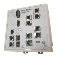
Connect to the switch using a USB micro-Type B port on the front panel.

RJ-45 Console Port

Connect to the switch using an RJ-45 console port on the front panel.

Install or Remove the SD Card

Install or Remove an SFP Module

Connect to SFP Module Ports

Connect to a Dual-purpose Port

Connect to 10;100 and 10;100;1000 Ports

Connect to 10 Base-T, 100 Base-TX, or 1000 Base-T Ports

Confirm Installation

Remove the Switch from the DIN Rail

Specifications

Additional Resources

Related product manuals