9
ASSEMBLY INSTRUCTIONS
B4
B4
AA
FF
II
AA
II
FF
G1 N1 B3
B3 B4
B4 B3
G1 N1 B3
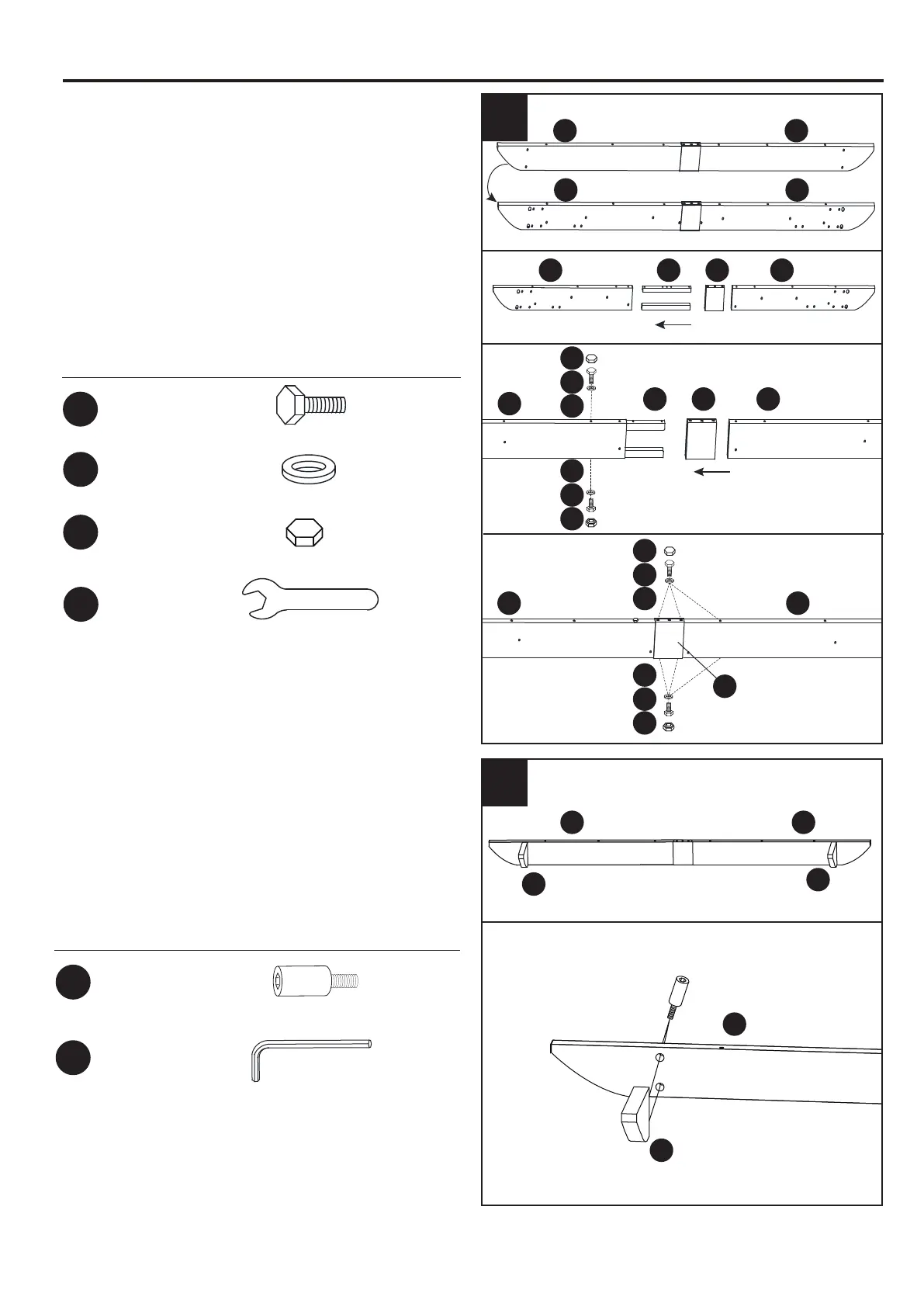
6. Insert the two Crossbeam Connector (G1) into
the Crossbeam Right (B4) and connect them with
Bolt (AA) and Flat
Washer
(FF). Insert the Top
Crossbeam Shield (N1) into the Crossbeam Right
(B4). Connect the Crossbeam Left (B3) / Top
Crossbeam Shield (N1) to the Crossbeam
Connector (G1) with Bolt (AA) and Flat
Washer
(FF). Tighten together with the wrench (NN). Place
Cap (II) on the Bolt (AA).
Hardware Used
M6 × 15 mm Bolt
X8
X8
X8
Cap
Washer
AA
FF
II
X1
Wrench
NN
AA
FF
II
6
AA
II
FF
B4 B3
N1
N1
II
B3
B3
C3
C3
C3
B4
7. Connect the Decoration Cap (C3) to the
Crossbeam (B3/B4) with Bolt (BB). Tighten
together with the
Allen Wrench (MM).
Hardware Used
M6 × 15 mm Bolt
X4
BB
X1
Allen Wrench
MM
7
 Loading...