Do you have a question about the Alliance Laundry Systems UT075E and is the answer not in the manual?
Details on hazard symbols and cautionary statements used throughout the manual.
Essential safety precautions for operating the tumble dryer to prevent hazards.
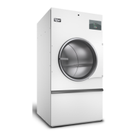
List of applicable models and instructions to refer to the serial plate for model numbers.
Guidance on locating the machine's serial plate for model and serial number information.
Description of the advanced graphical control interface and its capabilities.
Details on how the control behaves during and after power outages.
Information on the control's ability to communicate with PDAs/PCs via IrDA.
Explanation of programming and auditing via USB connection.
Details on network communication capabilities for remote control and diagnostics.
How the control collects and stores audit information.
Indicates how errors are shown on the display's upper left corner.
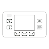
Description of the nine keypads and their functions for machine operation.
Overview of the different operational states the control can be in.
The initial state of the control upon powering the machine on.
How to pause and resume an active drying cycle.
Display message indicating a cycle was interrupted by power failure.
The mode where cycles are selected and started.
The display state while a cycle is actively running.
Indicates when a cycle has finished and the time elapsed.
Control checks for proper connection of key components after power-up.
Mode for running pre-programmed diagnostic test sequences.
Display and logging of all machine errors.
Indicates when IR communication is in progress.
Allows manual programming and diagnostics without external devices.
Feature to advance cycle steps faster via network or IR.
Enables manual access to diagnostic functions.
Displays active machine errors, prioritizing the highest priority error.
Post-cycle operation to reduce wrinkling by intermittent tumbling.
Additional tumbling after Anti-Wrinkle mode if enabled.
Step-by-step operation of a cycle based on its programmed type.
Cycles regulated by specific temperature and time duration.
Cycles that determine time based on temperature and dryness level.
Cycles that use programmed target moisture content for operation.
Procedure for selecting and starting a cycle from the Cycle Selection Menu.
Accessing Cycle Info and starting the selected cycle.
Displays attributes like cycle time, temperature, and speed before running.
Message shown if the loading door is open when starting or pausing.
Shows cycle name, status, temperature, and remaining time during operation.
Diagram illustrating navigation paths within the control's system menus.
Instructions for unlocking and tilting the control panel on stacked units.
Instructions for unlocking and removing the access panel on stand-alone units.
Access point to various control functions like Rapid Advance, Globals, and Diagnostics.
Menu to confirm or discard changes made during programming.
Displays the current information and status of a running cycle.
Allows viewing programmed temperature and moisture values for a cycle.
Enables modification of cycle parameters like temperature and moisture while running.
Shows the current state of all control inputs and outputs.
User interface for manually programming cycles or modifying existing ones.
Step-by-step guide for modifying existing or copied drying cycles.
Details on parameters for Time Dry, Cool Down, Auto Dry, Moisture Dry, and Reversing cycles.
List and descriptions of global machine settings and options.
Instructions for viewing machine usage statistics and cycle counts.
Displays model, serial number, install date, and software versions.
Lists recent errors and provides audit counts for error types.
Monitors control inputs and allows manipulation of machine outputs.
Guidance for running factory diagnostic test cycles.
Menu for selecting individual manual diagnostic tests.
Detailed descriptions of how to perform various diagnostic tests.
Checks machine configuration values related to machine type.
Checks machine configuration values related to machine capacity.
Shows which dipswitches are set on the control.
Checks machine configuration values for voltage supply.
Verifies the status of the Ignition Control Module (ICM) alarm.
Tests the status of heat interlock safety inputs.
Checks the status of the air flow switch (open or closed).
Tests cabinet limit, stove limit, and manual reset thermostats.
Tests the functionality of the fan, damper, and drive motors.
Tests the moisture sensor's ability to detect moisture levels.
Error related to the ignition control module or electric heat contactor.
Error triggered when a manual reset limit opens due to cabinet temperature.
Error when stove temperature causes a limit thermostat to open.
Error when cabinet temperature causes a limit thermostat to open.
Errors related to the air flow switch failing to open or close.
Errors when the output board fails to communicate with the ICM.
Specific error message for ICM communication failures.
Errors detected from the fan or drive motor communication.
Error when output board fails to communicate with fan or drive.
Errors occurring due to communication issues between control and computer.
Error when the output board detects a short circuit.
Error signal received from the output board indicating a malfunction.
Error when a thermistor is detected as shorted.
Error when a thermistor is detected as open.
Problem with communications between control and output board.
Error occurring during communication with the network.
Error when configuration data cannot be retrieved from the Machine ID chip.
Error that may occur during infrared communications.
Indicates the output board is not ready after communication establishment.
Error due to incorrect dip switch configuration for the machine.
Fatal alarm detected during a cycle, affecting machine operation.
Error when the control checks for the correct board ID or type.
Reference for fan/drive motor errors, their descriptions, and corrective actions.
Further reference for fan/drive motor errors, descriptions, and fixes.
Specific shorted output error code and its cause/correction.
Codes and fixes for various shorted output errors.
Error codes and corrective actions for ICM related faults.
Error codes and fixes for various output board malfunctions.
List of daily inspection items for machine upkeep and safety.
Options to reset global or cycle programming to factory defaults.
Table detailing parameters for moisture sensing drying cycles.
Table detailing parameters for Auto-Dry cycles (non-moisture sensing).
| Brand | Alliance Laundry Systems |
|---|---|
| Model | UT075E |
| Category | Dryer |
| Language | English |