AT-MC10x Series Media Converters Installation Guide
35
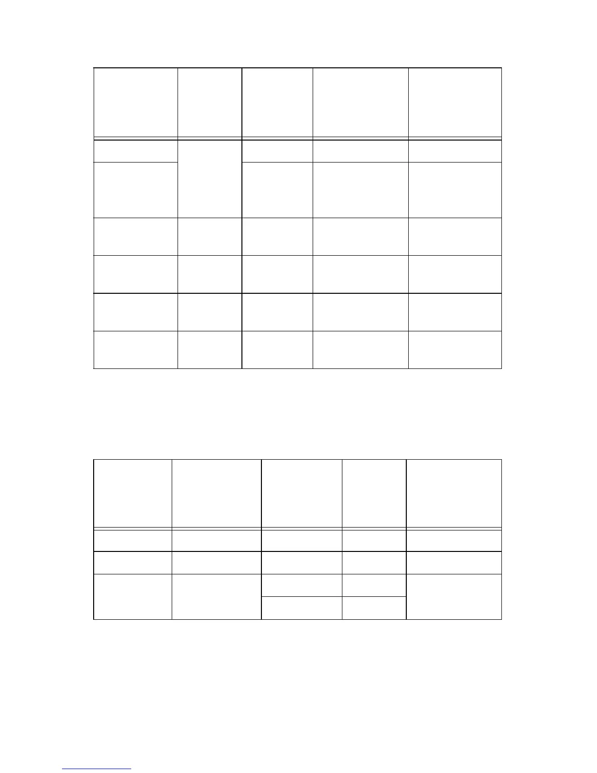
Table 12. Fiber Optic Loss Specifications (Benchmarks)
Table 11. Fiber Optic Datalink
Model
Fiber
Type
1
Max.
Power /
Link
Budget
Min. Distance
Spec.
2
Max. Distance
Spec.
AT-MC101XL 50/125
MMF
or
62.5/125
MMF
9.3 dB 0 2 km (1.2 mi)
AT-MC102XL 12.8 dB 0 2 km (1.2 mi)
AT-MC103XL 9/125
SMF
16.0 dB 0 15 km (9.4 mi)
AT-MC103LH 9/125
SMF
29.0 dB 10 km (6.2 mi) 40 km (24.8 mi)
AT-MC104XL 9/125
SMF
30.0 dB 15 km (9.4 mi) 75 km (46.5 mi)
AT-MC104LH 9/125
SMF
33.0 dB 17 km (10.5 mi) 90 km (55.8 mi)
1. MMF = Multimode Fiber / SMF = Single-mode Fiber
2. The recommended minimum range is stated in all cases where the maximum
transmitter output power exceeds the receivers saturation level. This is to pre-
vent blinding or burning out of the optical receiver on the far-end-node.
Fiber Type
1
1. MMF = Multimode Fiber / SMF = Single-mode Fiber
Fiber Optic
Diameter
(microns)
Optical
Wavelength
Typical
Loss
Factor
(dB/km)
Band-width
(Mhz * km)
MMF 50/125 1310 nm 1.00 400
62.5/125 1310 nm 1.00 500
SMF 9/125 1310 nm 0.40 N/A
1550 nm 0.30
 Loading...