xii
25
Glossary ......................................................................................................................25
31
Technical Support Fax Order ........................................................................... 31
33
CentreCOM AT-MR118FT and AT-MR128FT Manual Feedback ..........33
Index .............................................................................................................................35
List of Figures
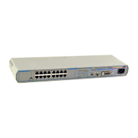
Figure 1: AT-MR118FT Front and Back Panels.............................................. 8
Figure 2: AT-MR128FT Front and Back Panels.............................................. 8
Figure 3: Typical Hub Configuration ............................................................. 11
Figure 4: 10BASE-T UTP Cabling Hub to MAU or NIC
(Straight-Through) ......................................................................... 19
Figure 5: 10BASE-T UTP Cabling Hub to Hub (Cross-Over) ...................... 19
Figure 6: Hub to MAU Wiring A. Usable and B. Unusable ......................... 21
Figure 7: Pin 1 Orientation on an RJ45 Connector ...................................... 22
List of Tables
Table 1: The AT-MR118FT and AT-MR128FT Characteristics ..................... 1
Table 2: CentreCOM Micro Repeater Dimensions .......................................... 2
Table 3: Usable and Unusable Twisted Pair Cable ...................................... 18
Table 4: MDI/MDI-X Switch Settings for Common Connection ................... 20
 Loading...