Operation
8
Link—Indicates when a valid link is detected by the receiver. The fiber optic Link
indicator must be illuminated at both ends of the segment for Ethernet data to
flow.
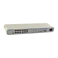
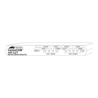
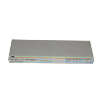
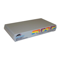
Figure 1 and Figure 2 show the indicators and ports for both the AT-MR118FT
and AT-MR128FT micro repeaters.
Figure 1: AT-MR118FT Front and Back Panels
Figure 2: AT-MR128FT Front and Back Panels
Setting Up Your Repeater
Here is an example procedure that results in the configuration in Chapter 4. The
sample configuration contains the following elements:
❑ An Attachment Unit Interface (AUI)/UTP hub connected to a 10BASE5
network in the main building
❑ An AT-MR118FT repeater in the main building
❑ An AT-MR128FT in the remote building
❑ An AUI/UTP hub in the remote building
PORT 1: 10BASE-T
TX RX
MR118FT
IEEE 802.3 MICRO REPEATER
CentreCOM
TM
PORT 2: 10BASE-FL/FOIRL
MR
118FT
IEEE 802.3
MICRO REPEATER
CentreCOM
POWER
RECEIVE
TRANSMIT
RECEIVE
TRANSMIT
LINKLINK
REPEATER
HALF FULL
RJ45 PIN-OUT
MDI MDI X
10BASE-FL/FOIRL
PORT 2
TX RX
10BASE-T
PORT 1
POWER
ON LINE
COLLISION
ON LINE
COLLISION
CentreCOM
TM
MR
128FT
IEEE 802.3 MICRO REPEATER
PORT 1: 10BASE-T
ON LINE
COLLISION
POWER
PORT 2: 10BASE-FL/FOIRL
TX RX
CentreCOM
TM
MR
128FT
IEEE 802.3 MICRO REPEATER
10BASE-FL/FOIRL
PORT 2
REPEATER
HALF FULL
10BASE-T
PORT 1
RJ45 PIN-OUT
MDI MDI X
POWER
RECEIVE
TRANSMIT
RECEIVE
TRANSMIT
LINK
LINK
COLLISION
ON LINE
COLLISION
 Loading...