507270-03Page 24 of 60 Issue 1621
Follow the next two steps when installing the unit in Non–
Direct Vent applications where combustion air is taken
from indoors and ue gases are discharged outdoors.
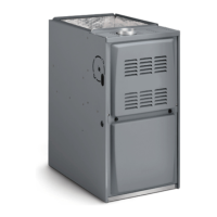
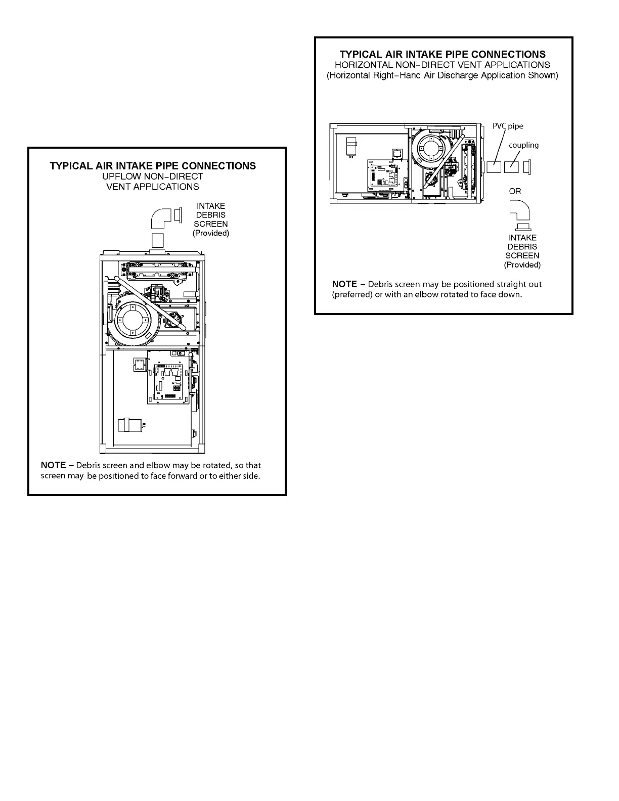
1. Use eld-provided materials and the factory-provided
air intake screen to route the intake piping as shown in
Figures 29 or 30. Maintain a minimum clearance of 3”
(76 mm) around the air intake opening. The air intake
opening (with the protective screen) should always be
directed forward or to either side in the upow position,
and either straight out or downward in the horizontal
position.
The air intake piping must not terminate too close
to the ooring or a platform. Ensure that the intake
air inlet will not be obstructed by loose insulation
or other items that may clog the debris screen.
2. Use a sheet metal screw to secure the intake pipe to
the connector, if desired
1. Use transition solvent cement or a sheet metal screw
to secure the intake pipe to the inlet air connector.
2. Route piping to outside of structure. Continue with
installation following instructions given in general guide
lines for piping terminations and in intake and exhaust
piping terminations for direct vent sections. Refer to
Tables 5 and 6 for pipe sizes.
Figure 29
Figure 30
 Loading...