6–12 Copyright © 1996 General Motors Corp.
AT 500, 1500 SERIES AUTOMATIC TRANSMISSIONS
(14) Install hold regulator valve 46 into Bore
L
(Figure 6–20). Into the same bore, install spring 47
(Foldout 11) and valve stop 48. Prior to transmission
S/N 113786, install valve plug 49. Beginning with
transmission S/N 113786, install washer 50 and ad-
justing ring 51. Compress adjusting ring 51 and install
retainer pin 52 through the valve body, across the re-
corded step of adjusting ring 51, and through the hole
in stop 48.
(15) Install valve stop 43 into Bore
M
(Figure
6–20). Into the same bore, install spring 44 (Foldout
11) and priority valve 45.
(16) Into Bore
N
(Figure 6–20), install either
modulator valve 8 (Foldout 11), spring 7, washer 6,
stop 5, and adjusting ring 4; or, actuating rod 80, mod-
ulator valve 81, spring 7, and adjusting ring 82. Com-
press adjusting ring 4 or 82 and install retainer pin 9
through the valve body, across the recorded step of ad-
justing ring 4 or 82, and through the hold in stop 5 or
at the outside end of valve 81.
(17) Install separator plate 2 onto valve body
11. Install valve body 10 onto separator plate 2.
NOTE:
Install six valve body bolts at various points
through the separator plate and valve body to align
separator plate.
(18) Install three
1
⁄
4
-20 x 1
3
⁄
4
inch bolts 3 to
retain valve body 10 and separator plate 2. Tighten the
bolts to 8–12 lb ft (11–16 N·m). The assembled valve
body is shown in Figure 6–21.
(19) Install selector valve 53 (Foldout 11 into
the assembled valve body and retain it with a rubber
band, tape, or soft wire to prevent its dropping out dur-
ing handling.
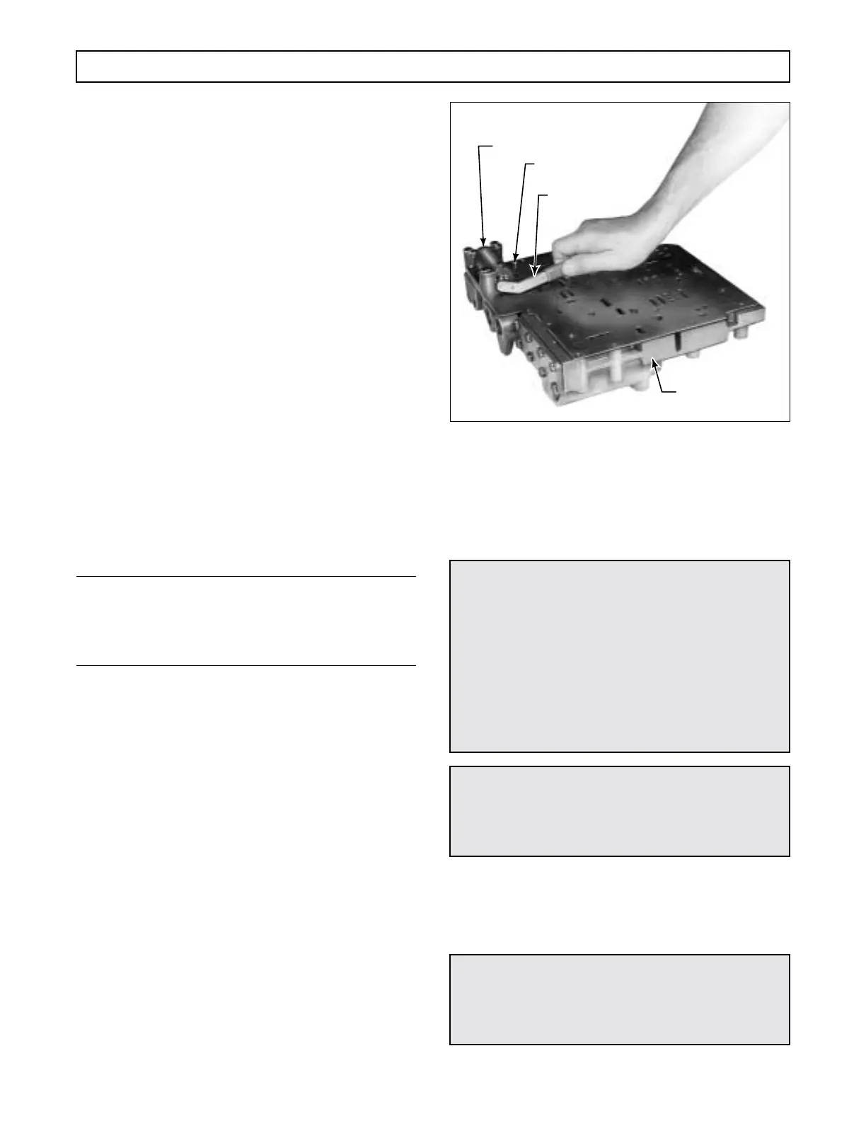
(20) Use special tool J 24314, recheck the po-
sitions of all adjusting rings (Figure 6–21) with the po-
sitions recorded before disassembly.
(21) For ease of handling, install valve body
lifting tool J 29863 into the drilled boss in the center
of the valve body. Put the assembled valve body into a
plastic bag or other dirt-proof, lint-free wrapping until
ready to install it.
Figure 6–21. Adjusting Modulator Valve Ring
6–7. RETARDER CONTROL
VALVE BODY
a. Disassembly
(Foldout 13)
(1) Restrain plug 19 and remove pin 22.
(2) Remove plug 19, priority valve 20, and
spring 21.
CAUTION:
The retarder control valve body assembly con-
tains springs and other parts, some of which are
similar and can be mistakenly interchanged. If
parts are not reinstalled in the same locations
from which they were removed, the calibration
of retarder control valve body functions will be
lost. Tag each part at removal with its item num-
ber in Foldout 13 to simplify correct reassembly
of the valve body components.
WARNING!
Priority valve 20 and plug 19 are spring-loaded
and must be restrained while pin 22 is being re-
moved.
WARNING!
Regulator valve 24 and plug 27 are spring-loaded
and must be restrained while pin 22 is being re-
moved.
H02932
MODULATOR VALVE
CONTROL VALVE
ADJUSTING RING
TOOL J 24314
GOVERNOR CHECK VALVE
BALL (EARLIER MODELS)
 Loading...


