12
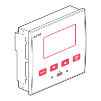
Commands menu
– The commands menu allows executing some occasional operations like reading peaks resetting, counters clearing, alarms reset, etc.
– If the Advanced level password has been entered, then the commands menu allows executing the automatic operations useful for the device conguration.
– The following table lists the functions available in the commands menu, divided by the access level required.
– With controller in MAN mode, press the MODE button for 5 seconds.
– Press ▲ to select CMD.
– Press MAN-AUT to access the Commands menu.
– Select the desired command with MODE or MAN-AUT.
– Press and hold for three seconds ▲ if you want to execute the selected command. ALPTEC shows OK? with a countdown.
– If you press and hold ▲ until the end of the countdown the command is executed, while if you release the key before the end, the command is canceled.
COD COMMAND
PWD.
ACCESS LEVEL
DESCRIPTION
C01 RESET MAINTENANCE Adv Reset maintenance service interval.
C02 RESET STEP COUNT Adv Reset step operation counters.
C03 RESET STEP TRIMMING Adv Reload originally programmed power into step trimming.
C04 RESET STEP HOURS Adv Reset step operation hour meters.
C05 RESET MAX VALUES Adv Reset maximum peak values.
C06 RESET WEEKLY TPF Adv Resets weekly total power factor history.
C07 SETUP TO DEFAULT Adv Resets setup programming to factory default.
C08 SETUP BACKUP Adv Makes a backup copy of user’s setup parameters settings.
C09 SETUP RESTORE Adv Reloads setup parameters with the backup of user settings.
Alarm description
COD ALARM DESCRIPTION
A01 Undercompensation All the available steps are connected but the cosphi is still more inductive than the setpoint.
A02 Overcompensation All the steps are disconnected but the cosphi is still more capacitive than the setpoint.
A03 Current too low The current owing in the current inputs is lower than minimum measuring range. The plent should be
o-load.
A04 Current too high The current owing in the current inputs is higher than maximum measuring range.
A05 Voltage too low The measured voltage is lower than the threshold set with P.42.
A06 Voltage too high The measured voltage is higher than the threshold set with P.41.
A07 Panel temperature too high The panel temperature is higher than threshold set with P.39.
A08 Capacitor current overload The calculated capacitor current overload is higher than threshold set with P.32 and P.33.
A09 No-Voltage release A no-voltage release has occoured on the line voltage inputs, lasting more than 8ms.
A10 Voltage THD too high The THD of the plant voltage is higher than the threshold set with P.43.
A11 Current THD too high The THD of the plant current is higher than the threshold set with P.44.
A12 Maintenance requested The maintenance interval set with P.45 has elapsed. To reset the alarm use the command C.xx (see
Command menu)
A13 Step failure The residual power of step xx is lower than minimum threshold set with P.40.
COD DESCRIPTION ENABLE ALARM RELAY DISCONNECTION DELAY
A01 Undercompensation •• 15 min
A02 Overcompensation •• 120 s
A03 Current too low •• 5s
A04 Current too high •• 120 s
A05 Voltage too low •••0s
A06 Voltage too high •••0s
A07 Capacitor current overload •••30 s
A08 Temperature too high •••60 s
A09 No-Voltage release •••0s
A10 Voltage THD too high •••5s
A11 Current THD too high •••5s
A12 Maintenance requested •• 0s
A13 Step failure •••5s
Alarms
– When an alarm is generated, the display will show an alarm icon, the code and the description of the alarm in the language selected.
– If the navigation keys in the pages are pressed, the scrolling message showing the alarm indications will disappear momentarily, to reappear again after a
few seconds.
– Alarms are automatically resetted as soon as the alarm conditions that have generated them disappear.
– In the case of one or more alarms, the behaviour of the ALPTEC depends on the properties settings of the active alarms.
2014-AT3-5-01-ANG.indd 12 20/03/14 11:46
 Loading...