13
Installation
– ALPTEC is designed for ush-mount installation. With proper mounting, it guarantees IP54 front protection.
– From inside the panel, for each four of the xing clips, position the clip in one of the two sliding guide, then press on the clip corner until the second guide
snaps in.
– Push the clip forward pressing on its side and making it slide on the guides until it presses completely on the internal surface of the panel.
– For the electrical connection see the wiring diagrams in the dedicated chapter and the requirements reported in the technical characteristics table.
CX02 Dongle usage
– The CX02 dongle oers WiFi Access point capability for connection to PC, Tablet or smartphones. In addition to this function it also oer the possibility to
store and transfer a block of data from/to the DCRL.
– Insert the interface CX02 into the IR port of DCRL on the front plate.
– Switch CX02 on by pressing the button for 2 sec.
– Wait until the LINK LED becomes orange ashing.
– Press 3 times consecutively and fast the dongle button.
– At this point the display of the DCRL show
s the rst of the 6 possible commands (D1…D6).
– Press ▲▼to select the desired command.
– Press MAN-AUT to execute the selected command. The unit will prompt for a conrmation (OK?). Press once again MAN-AUT to conrm or MODE to cancel.
– The following table lists the possible commands:
COD COMMAND DESCRIPTION
D1
SETUP DEVICE
➔ CX02
Copies Setup settings from DCRL to CX02.
D2
SETUP CX02
➔ DEVICE
Copies Setup settings from CX02 to DCRL.
D3
CLONE DEVICE
➔ CX02
Copies Setup settings and working data from DCRL to CX02.
D4
CLONE CX02 ➔ DEVICE
Copies Setup settings and working data from CX02 to DCRL.
D5 INFO DATA CX02 Shows information about data stored into CX02.
D6 EXIT Exits from dongle menu.
For additional details see CX02 Operating manual
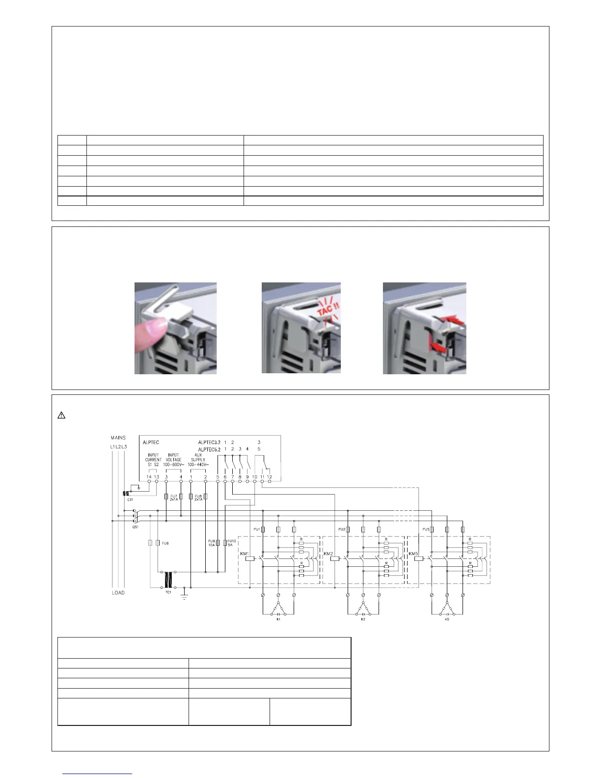
Wiring diagrams
WARNING! Disconnect the line and the supply when operating on terminals.
Standard Three-phase wiring
Typical diagram - do not represent the internal connexion of our capacitor banks
THREE-PHASE CONNECTION TYPE “A”– P.11 set to A.con (default)
Default wiring conguration for standard applications.
Voltage measure 1 ph-to-ph voltage reading L1-L2
Current measure L3 phase
Phase angle oset
Between V (L1-L2 ) and I (L3) ➔ 90°
Capacitor overload current measure 1 reading calculated on L1-L2
Parameter setting P.03 = L3
P.05 = L1-L2
P.24 = 3PH
NOTES : – For three-phase connection, the voltage input must be connected phase to phase; the current transformer must be connected on the remaining phase.
– The polarity of the current/voltage input is indierent.
2014-AT3-5-01-ANG.indd 13 20/03/14 11:46
 Loading...