14
Wiring diagrams (continued)
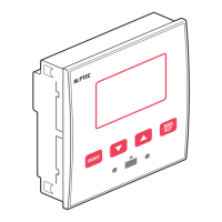
Single-phase wiring
Typical diagram - do not represent the internal connexion of our capacitor banks
SINGLE-PHASE CONNECTION
Wiring conguration for single-phase applications
Voltage measure 1 phase voltage reading L1-N
Current measure L1 phase
Phase angle oset
Between V (L1-N ) and I (L1)
➔ 0°
Capacitor overload current measure 1 reading calculated on L1-N
Parameter setting P.03 = L1
P.05 = L1-N
P.24 = 1PH
NOTES: – IMPORTANT: The polarity of the current/voltage input is indierent
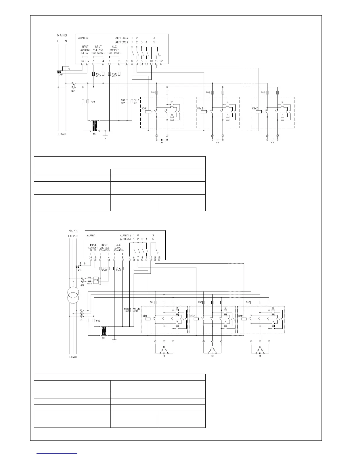
Conguration with MV measurement and correction on LV side
Typical diagram - do not represent the internal connexion of our capacitor banks
Conguration with MV measurement and LV correction
Voltage measure 3 ph-to-ph voltage reading L1-L2, L2-L3, L3-L1
on MV side
Current measure L1-L2-L3 phase
Phase angle oset 90°
Capacitor overload current measure 1 reading on L1-L3, LV side
Parameter setting P.03 = L3
P.05 = L1-L2
P.24 = 3PH
P.34 = VT primary
P35 = VT secondary
NOTES: IMPORTANT! – The polarity of the current/voltage input is indierent.
2014-AT3-5-01-ANG.indd 14 20/03/14 11:46
 Loading...