583032600bUK– Translation into English of the original German operating manual – Subject to technical change without notice.
Funktion
Raumbedieneinheit
A
+12V
2
GND
1
B
RBE
LIN-Bus
RJ45
4
3
RBE
RJ45
A2
Bezeichnung
Legende: DE831183
Bedienteil
1
2
3
4
RBE
Raumbedieneinheit RBE
Datum
831183
Achim Pfleger 24.07.2013
- PEP 008/2013
Bl von Anz
Name
1 2 3 4 5 6 7 8 9 10 11 12 13 14 15 16
1 2 3 4 5 6 7 8 9 10 11 12 13 14 15 16
1/1
1
Datum
Bearb.
Änderung
24.07.2013
Zustand
-
Blatt-Nr.
A. Pfleger
Funktion
Raumbedieneinheit
A
+12V
2
GND
1
B
RBE
LIN-Bus
RJ45
4
3
RBE
RJ45
A2
Bezeichnung
Legende: DE831183
Bedienteil
Raumbedieneinheit
RBE
Raumbedieneinheit RBE
Datum
831183
Achim Pfleger 24.07.2013
- PEP 008/2013
Bl von Anz
Name
1 2 3 4 5 6 7 8 9 10 11 12 13 14 15 16
1 2 3 4 5 6 7 8 9 10 11 12 13 14 15 16
1/1
1
Datum
Bearb.
Änderung
24.07.2013
Zustand
-
Blatt-Nr.
A. Pfleger
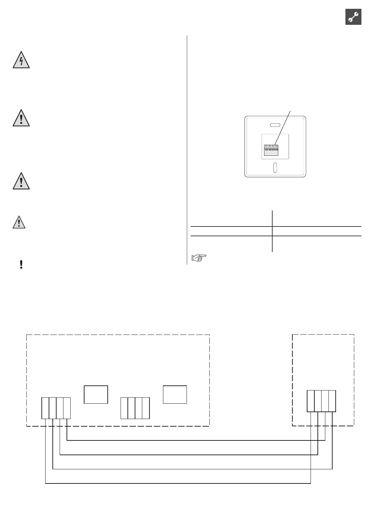
CONNECTING THE COMMUNICATIONS AND POWER SUPPLY
Communication and power supply take place via the RS485 interface
attached to the heat pump control unit. The RBE must be connected to
this interface.
Use a exible cable type (LiYY, EKKX) or equivalent. The required and at
the same time maximum cable cross-section 0.5 mm².
Connect as shown in the following terminal diagram:
Terminal
Elektrischer Anschluss
HINWEIS!
Alle elektrischen Anschlüsse müssen von einem
geprüften Elektriker ausgeführt werden.
Bei der Elektroinstallation und beim Verlegen
der Leitungen sind die geltenden Vorschriften
zu berücksichtigen.
F1145/F1245/F370/F470/F750 darf bei der Instal-
lation von RMU 40 nicht mit Spannung versorgt
werden.
Anschluss von Kommunikation und Span-
nungsversorgung
Die Klemme in RMU 40 wird mit Klemme X4:9–12 an
der Eingangskarte (AA3) in der Wärmepumpe verbunden.
Verwenden Sie Kabeltyp LiYY, EKKX oder gleichwertig.
RMU 40
+12V GND B A
$QVFKOXVVNOHPPH
F1145
F1145RMU 40
A
B
GND
+12V
8
9
10
7
11
12
13
$$;
508b )
$$;
F1245
+12V
ABGND
12
1110 13987
F1245
RMU 40
508b
)
$$;
$$;
F370/F470
+12V
ABGND
12
1110 13987
F1245
RMU 40
508b
))
$$;
$$;
F750
+12V
ABGND
12
1110 13987
F1245
RMU 40
508b
)
$$;
LEK
$$;
Mehrere RMU 40/SMS 40-Einheiten
Soll eine weitere RMU 40-Einheit bzw. SMS 40-Einheit
mit F1145/F1245/F370/F470/F750 verbunden werden,
ist diese von der Anschlussklemme in der ersten Einheit
umzusetzen. Es können maximal zwei Einheiten ange-
schlossen werden.
)))))
508b
606
508b
606
Värmepump
RMU 40
RMU 40
8
9
10
7
11
12
13
A
B
GND
+12V
A
B
GND
+12V
$$;
508b
508b
Technical data
Surface-mounted frame made of plastic
WxHxD (mm)
85x85x35
RBE dimensions WxHxD (mm) 85x85x14
Nominal voltage 12 V DC 40 mA
(Power supply from the heat pump)
To commission or start up the RBE, follow the procedure
described on page 9.
Electrical connection
DANGER!
Risk of fatal electric shock!
All electrical connection work must be carried out
by qualied electricians only.
Before opening the unit, disconnect the system
from the power supply and prevent it from being
switched back on again!
WARNING!
Note and follow the relevant EN, VDE and/or local
safety regulations during installation and when car-
rying out electrical work.
Note and follow the technical connection condi-
tions of the responsible power supply company!
WARNING!
Only qualied personnel (trained heating or refrig-
eration engineer or electrician) may carry out work
on the unit and its components.
CAUTION!
A cable with a small cross-section reduces the approved
length of the connection cable. If the cable is too long the
RBE may not work!
ATTENTION
Electrical work on the room control unit may only be car-
ried out by the authorised service personnel or specialised
rms, which have been authorised by the manufacturer.
max. 30 m*
* The 30 m between the heat pump (WP) control unit and the RBE are only allowed if the connection cable between the WP
control unit and the master board of the WP control is ≤ 3m.
Room control unit