If any of the following does NOT occur, depress power OFF switch immediately and investi
gate before proceeding:
* The blower starts (note air exhausting above tubes.
* The multimeter bargraph automatically displays HV; it should indicate approximately
2.8 KV.
* The WATT LED is lighted.
IMPORTANT: EXHAUST AIR MUST BE DETECTABLE FROM THE TOP VENTS: If it is
not, TURN OFF the amplifier and verify that the exhaust chimneys are properly positioned
over the tubes. When the warm up delay is complete (about 150 seconds), the WATT LED
will extinguish. The ETO 91/3 is now "ready". ^
2. Tuning Up for Operation at 1,500 Watts RF Output
1) Preset BAND, TUNE, and LOAD controls to the nominal positions given in TABLE I,
below.
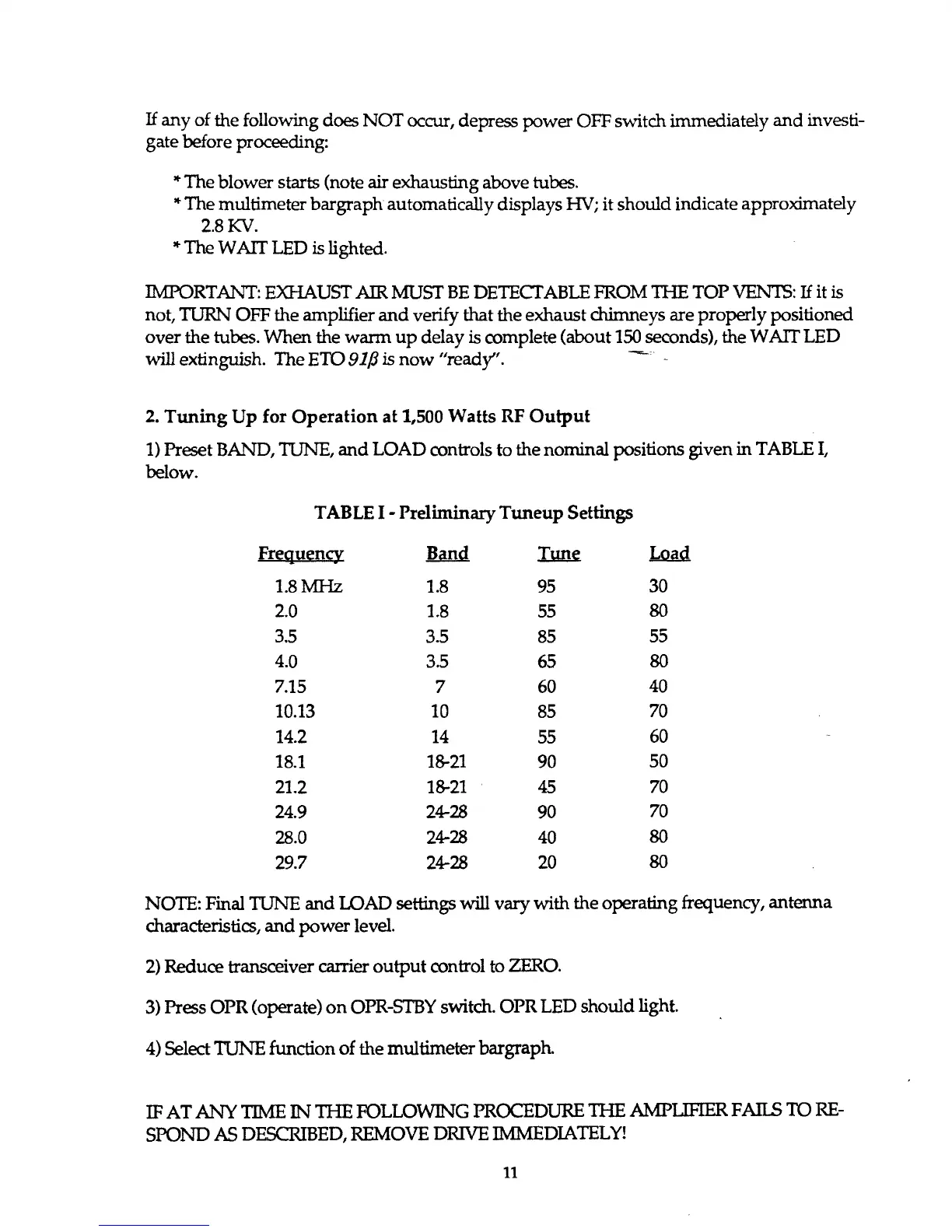
TABLE I - Preliminary Tuneup Settings
Frequency
Band
Tun?
Lo?d
1.8 MHz 1.8 95
30
2.0 1.8 55
80
3.5 3.5 85
55
4.0
3.5
65
80
7.15 7 60
40
10.13 10 85
70
14.2 14
55
60
18.1 18-21 90
50
21.2
18-21 45
70
24.9
24-28 90
70
28.0
24-28
40
80
29.7
24-28
20
80
NOTE: Final TUNE and LOAD settings will vary with the operating frequency, antenna
characteristics, and power level.
2) Reduce transceiver carrier output control to ZERO.
3) Press OPR (operate) on OPR-STBY switch. OPR LED should light.
4) Select TUNE function of the multimeter bargraph.
IF AT ANY TIME IN THE FOLLOWING PROCEDURE THE AMPLIFIER FAILS TO RE
SPOND AS DESCRIBED, REMOVE DRIVE IMMEDIATELY!
11