10
3.4. Product Installation and Operation
3.4.1. Installation Procedure:
1. Open package and note the packaging layers. Keep the box and packaging
material in case further transportation is required.
2. Check for damage to the ATS from shipping and handling. Please contact your
local distributor if the product is damaged.
3. Check the input power cable/socket and output socket of the delivered ATS
model with your order.
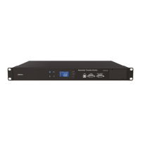
4. Affix the backplate (Figure 1) onto the ATS (Figure 2). Affix the ATS onto the
frame of the chassis (Figure 3).
5. Insert the load plugs into the ATS sockets labeled "OUTPUT" and spreading
them as evenly as possible.
6. Check that the total load does not exceed ATS specifications (e.g. voltage,
current).
7. Supply power to the ATS. The ATS automatically boots up after 1 second and
supplies the capacity power to the connected load.
Figure 1 & 2
Figure 3
11
3.4.2. Boot up
Once input power is connected, the ATS automatically boots up. The LCD display
during boot is as shown in Figure 4 and all LEDs ( , , ) are lit. LCD
display is as shown in Figure 5 after boot up, only the LEDs for Power A ( )
and Power B ( ) are lit.
Figure 4 Figure 5
3.4.3. Switch input source
This products supports manual switching between power supplies as instructed
below:
Push and hold the
button for 2 seconds until you hear two short beeps.
The system then needs to reconfirm the power transfer (LCD display as shown in
Figure 6), so push and hold the
button for 2 seconds to confirm. The
system will switch to the other input (LCD display as shown in Figure 7) if the
power supply is normal, otherwise the transfer is not made and a warning is shown
(LCD display as shown in Figure 8).
Figure 6 Figure 7 Figure 8