13
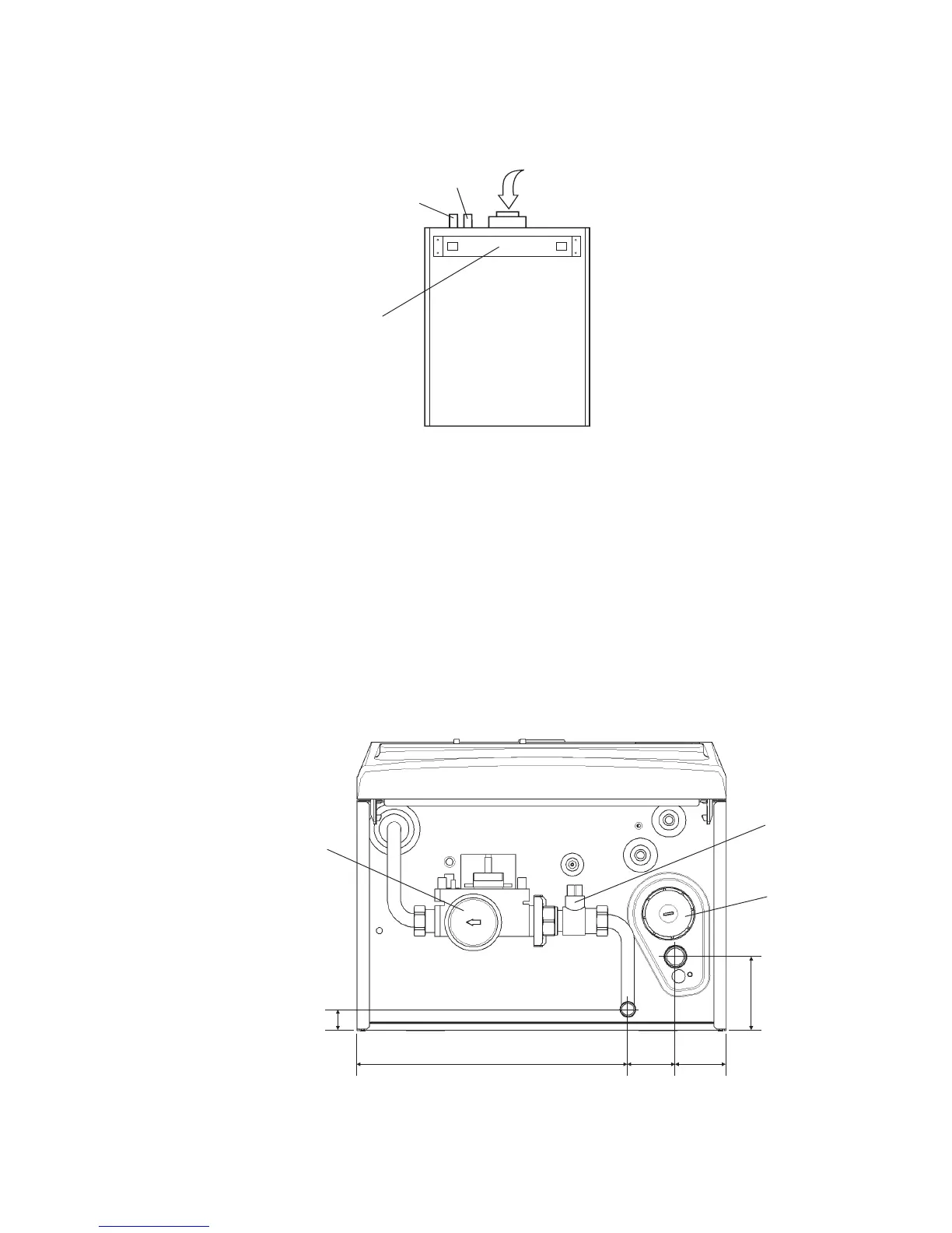
Fig. 13
A - Gas valve
B - Gas isolating valve
C - Condensate trap
4.4 FIT THE BOILER - Refer to Fig. 11
1. Lift the boiler and locate it on the mounting bracket. Fit the bottom screws to secure the boiler in position.
Alpha CD13R, 18R, 24R - Installation
Fig. 12
4.5 CONNECT THE PIPEWORK - Fig. 13
1. Thoroughly flush out all the water pipework. Refer to Section 3.9.
2. The gas isolation valve has been factory fitted, however, check that the connections underneath the boiler have been
tightened.
Note: When soldering to the boiler union bend, ensure the bend is not connected to the valve, otherwise the internal seals
may be damaged.
3. Connect the system pipework to the boiler.
Note: Ensure the flow and return pipes are correctly connected to the boiler. Refer to Fig. 12.
4. Connect the 22 mm condensate trap drain pipe to the condensate discharge pipe.
Ensure that the condensate discharge pipe is as required in Section 3.11.
Pour at least 0.5 litre of water into the flue duct, as shown in Fig. 12, and check the condensate discharge pipe for soundness.
5. Ensure that the gas isolation valve is closed (spindle flats at right angles to valve) and do not turn on the gas supply at this stage.
A
B
C
20
235
105 50
85
Pour water into flue duct
Rear view of boiler
Boiler locating
bracket
CH flow
CH return