12
Alpha CD13R, 18R, 24R - Installation
4 INSTALLATION
4.1 UNPACKING
1. The boxes required when the boiler is installed with a horizontal flue are as follows:-
Box 1 Cased boiler fitted with gas isolation valve, gas union and washers
Mounting bracket plus screws and wall plugs, 15 mm gas union bend
Literature pack and Wall template
Box 2 CD Easy-Flue 500 mm or CD Easy-Flue 1000 mm. Both include 90° bend and horizontal flue terminal
Note: NOT required for vertical flue
Notes: a. All flues must be suitable for CD condensing boilers.
b. CD 750 mm and 1000 mm flue extensions are available, if required.
2. Unpack boiler and remove the loose items packs and mounting bracket.
Note: To prevent any damage being caused, ensure the gas union bend is removed before standing the boiler in an
upright position.
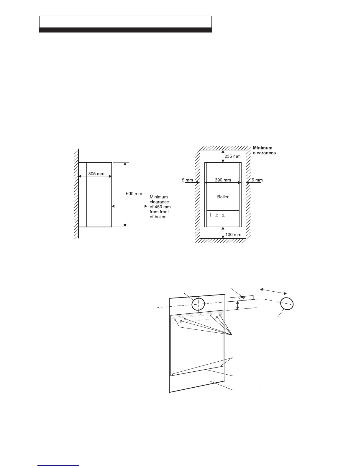
4.2 CLEARANCES REQUIRED - Fig. 10
Fig. 10
4.3 PREPARE THE WALL - Figs. 11, 12
1. Decide upon the position of the boiler taking
into account the clearances required for
servicing and the flue terminal position.
2. Tape the template to the wall (ensure it is
level and the right way up) and mark the
position of the holes for the boiler mounting
bracket and bottom fixings. If rear exit flue is
used, mark the position of the hole for the
flue.
3. Side exit flue - Continue the horizontal centre
line of the flue across the wall to the side wall,
then along the side wall 160 mm for the CD13R
and CD18R or 130 mm for the CD24R (ensure
the lines are horizontal). This will give the position
of the centre of the hole for the flue.
4. Cut the 110 mm diameter hole (or use a 107
mm core drill) in the wall for the flue.
Notes: a. Ensure the hole is horizontal.
b. For internal fitting of the flue, using
the flue sealing collar supplied, cut a
130 mm dia. flue hole using a 127 mm core drill.
5. Drill the fixing holes (10 mm dia.) to accept the No.10 plugs supplied. Using the screws supplied, fit the mounting bracket.
Fig. 11