21
Alpha CD13R, 18R, 24R - Routine Servicing
To ensure efficient operation of the boiler it is recommended that it is checked and serviced as necessary at regular intervals.
The frequency of servicing will depend upon the particular installation conditions and usage, but in general once per year
should be adequate.
It is the law that any service work must be carried out by a competent person, i.e. CORGI registered personnel.
Warning: Before servicing the boiler, isolate the electrical supply and close the boiler gas service cock. Allow the boiler to cool.
The data label is positioned on the underneath of the bottom casing.
Always test for gas soundness after servicing any gas carrying components.
Always carry out electrical system checks i.e. Earth Continuity, Resistance to Earth, Short Circuit and Polarity with a suitable
meter after servicing.
7.1 IMPORTANT NOTES PRIOR TO SERVICING
1. Check the flue terminal outside and ensure it is not blocked.
2. Run the boiler and check the operation of its controls.
3. Refer to Fig. 2 for location of flue sampling point.
4. Ensure that all system connections and fittings are sound. Remake any joints and check the tightness of any fittings that
may be leaking.
5. Check that the condensate trap drain pipe is connected and all joints are sound.
6. Record details of the service in the Service Record Section on back page of this manual and in the Benchmark Log Book.
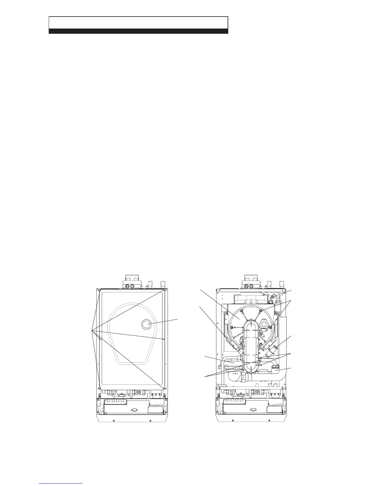
7.2 PREPARE FOR SERVICING - Fig. 25
1. Ensure the electrical supply is isolated and the gas supply is off.
2. Remove the screw at the top centre of the front panel, then lift it up and remove the panel. Release the two screws
securing the control panel and lower the panel.
3. Remove the six screws securing the room sealed chamber panel and remove the panel, taking care not to damage the seal.
4. Disconnect the gas supply pipe union.
5. Remove the two screws securing the fan assembly to the combustion chamber front.
6. Remove the two pressure tubes, noting their positions.
7. Disconnect the electrode lead from the ignition generator and the in-line connector to the flame sensing electrode.
8. Remove the six nuts and washers securing the combustion chamber front assembly and remove the assembly.
7 ROUTINE SERVICING
Fig. 25
Room sealed panel
fixing screws
Six nuts and washers
securing combustion
chamber front
assembly
Gas pipe
union
Pressure tube
connections
Fan assembly
fixing screws
Ignition generator
Fan
assembly
Combustion
chamber front
assembly
Viewing
window
Drain valve
Condensate trap