3
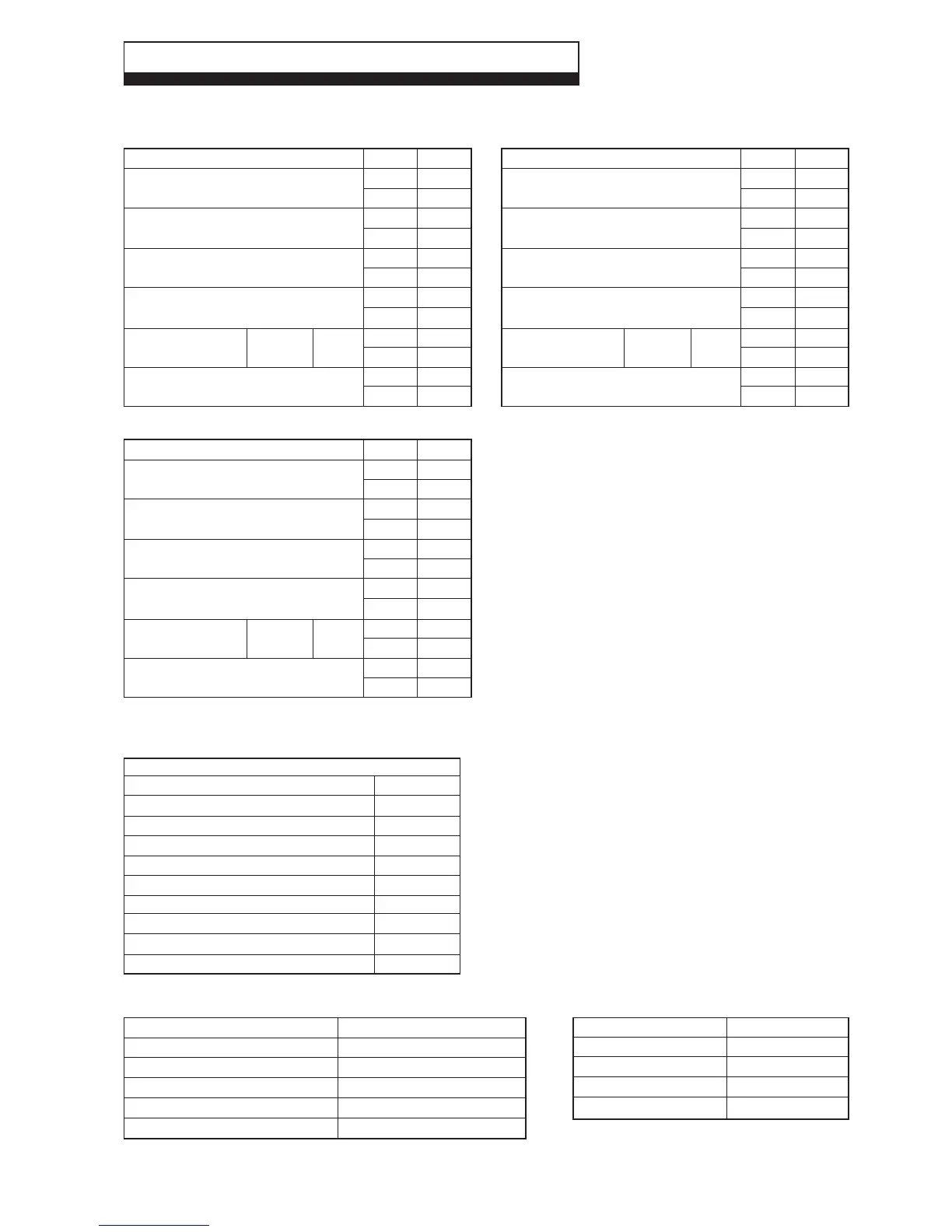
2.1 PERFORMANCE - NATURAL GAS (CAT: 12H 2H - G20 - 20 mbar)
2 TECHNICAL DATA
Alpha CD13R, 18R, 24R - Technical Data
Alpha CD13R
MAX.
13.8
47 000
12.4
42 300
13.1
44 700
12.1
41 300
1.7
0.68
1.31
46.2
MIN.
6.2
21 100
5.6
19 100
5.9
20 100
5.4
18 400
0.4
0.16
0.6
21.2
Room sealed
chamber panel
fitted
Central Heating
Heat Input (H
s
)kW
(Gross) Btu/h
Heat Input (H
i
)kW
(Net) Btu/h
Heat Output (H
s
condensing) kW
(50°C/30°C) Btu/h
Heat Output (H
i
non-condensing) kW
(80°C/60°C) Btu/h
Differential Burner mbar
Pressure in wg
Gas Rate m³/h
ft³/h
Alpha CD18R
MAX.
20.4
69 600
18.4
62 800
19.6
66 800
18.0
61 400
3.54
1.42
1.94
68.5
MIN.
6.2
21 100
5.6
19 100
5.9
20 100
5.4
18 400
0.4
0.16
0.6
21.2
Room sealed
chamber panel
fitted
Central Heating
Heat Input (H
s
)kW
(Gross) Btu/h
Heat Input (H
i
)kW
(Net) Btu/h
Heat Output (H
s
condensing) kW
(50°C/30°C) Btu/h
Heat Output (H
i
non-condensing) kW
(80°C/60°C) Btu/h
Differential Burner mbar
Pressure in wg
Gas Rate m³/h
ft³/h
Alpha CD24R
MAX.
26.6
90 700
24
81 900
25.6
87 300
23.5
80 200
5.6
2.24
2.54
89.7
MIN.
7.5
25 600
6.8
23 200
7.2
24 600
6.5
22 200
0.6
0.24
0.72
25.4
Room sealed
chamber panel
fitted
Central Heating
Heat Input (H
s
)kW
(Gross) Btu/h
Heat Input (H
i
)kW
(Net) Btu/h
Heat Output (H
s
condensing) kW
(50°C/30°C) Btu/h
Heat Output (H
i
non-condensing) kW
(80°C/60°C) Btu/h
Differential Burner mbar
Pressure in wg
Gas Rate m³/h
ft³/h
Central Heating (Sealed System)
Max. Working System Pressure
Min. System Pressure
Max. System temperature
Pressure Relief Valve Setting
Expansion Vessel Size (pre-charge press.)
Flow Connection
Return Connection
Relief Valve Connection
Recommended System Pressure (cold)
CH Water Temp. (Approx. max.)
2.5 bar
0.5 bar
82°C
3 bar (44 PSI)
8 L at 1.0 bar
22 mm
22 mm
15 mm
1.0 bar
80°C (176°F)
2.2 SEALED SYSTEM
Note: Refer to Fig. 5 when using with a fully
pumped open vented system.
Burner
Main Heat exchanger
Main Burner Injector CD13R/18R
CD24R
Flue - Outer Duct
Flue - Inner Duct
2.3 COMPONENTS
2.4 ELECTRICAL
Supply
External Fuse
Power Consumption
Internal Fuse
Electrode Spark Gap
230/240 V ~ 50 Hz
3 A
55 W
F2 A
3 - 4 mm
Stainless steel
Stainless steel
5.1 mm
5.25 mm
White
Plastic
Note: When installed using a sealed heating system, a sealed system kit must be fitted.