4
L
N
1
2
F2A
3
4
L
N
Alpha CD13R, 18R, 24R - Technical Data
Fig. 1
600 mm
390 mm
305 mm
15 mm
22 mm
1.6 L
100 mm
60 mm
Case Dimensions Height
Width
Depth
Gas Connection CD13R/18R
CD24R
Primary Water Content
Air Duct Diameter
Flue Duct Diameter
2.6 GENERAL
2.7 FLUE LENGTHS
CD Easy-Flue 500 mm with terminal and 90° bend. A CD Easy-Flue 1000 mm with terminal and 90° bend is also available.
CD 750 mm and CD 1000 mm flue extensions are available.
Length of Flue Required:-
Rear Flue (includes terminal) = wall thickness + 170 mm (or 140 mm for CD24R)
Side Flue (includes terminal) = wall thickness + distance between wall and side of boiler + 200 mm
Vertical Flue = distance from top of boiler side panel to required roof position minus 1 m for vertical terminal assembly
Maximum horizontal flue length = 12 m.
Maximum vertical flue length including terminal is 15 m.
Each additional CD 90° Bend is equivalent to 1.3 m of flue length.
Each CD 45° Bend is equivalent to 0.9 m of flue length.
The CD Vertical Flue terminal assembly is equivalent to 1 m of flue length.
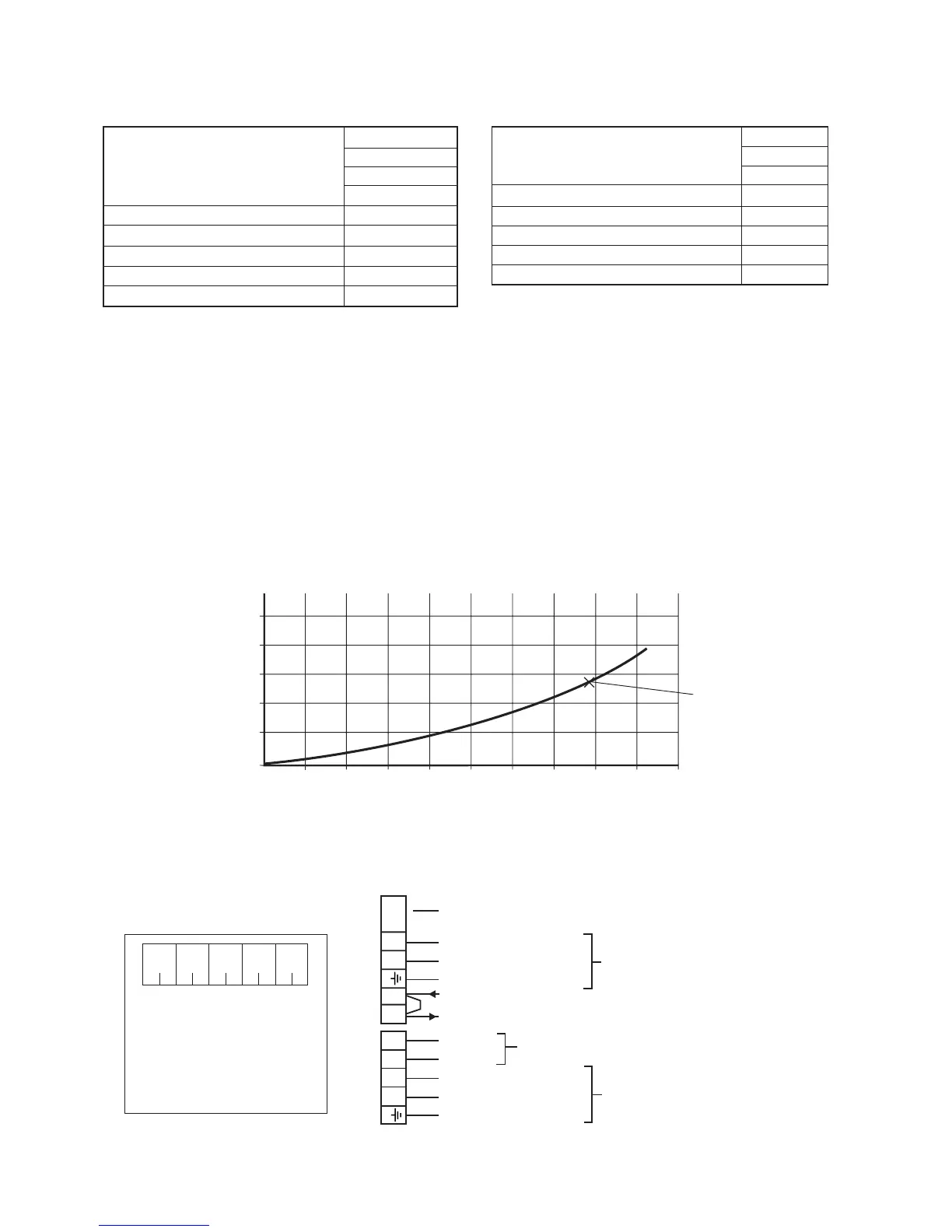
2.8 PRESSURE LOSS ACROSS BOILER
Boiler terminal block
Clock connections
2.9 ELECTRICAL CONNECTIONS
Note: This Appliance Must Be Earthed
An optional integral two channel Clock kit (Part No. 6.1000220) is available if required.
Note: Only use the Alpha two channel clock. Do not fit any single channel clocks.
Min. Clearances for Servicing Top
(from casing) Bottom
Sides
Front
Flue Terminal Size
Flue Terminal Protruding
Hole Size Required For Flue Assy.
Lift Weight CD13R/18R
CD24R
2.5 INSTALLATION
235 mm
100 mm
5 mm
450 mm
100 mm Dia.
100 mm
110 mm Dia.
27 kg
28 kg
1. Ensure wires are connected
correctly
2. Only fit the Alpha recommended
2 channel clock. Other clocks
could cause damage.
WARNING
12345
Internal 2 Channel Clock Terminals
White
wire
Grey
wire
Black
wire
Blue
wire
Brown
wire
Fuse - Always fit fast blow 2 A
230/240 V ~ 50 Hz
Fuse supply 3 A
Note: To connect external
control, remove link from
terminals 1 and 2 and
connect a 230/240 V
switched live to terminal 1
0
0 200 300100 400 500 600 700 800 900 1000
0.5
1.0
1.5
2.0
2.5
Flow rate (litres/hr)
Pressure loss
(metres head of water)
20°C System design
temperature difference
Note: The pump must
always be connected
to this terminal block
Live (Brown wire)
Neutral (Blue wire)
Earth (Green/Yellow wire)
Switched Live
230/240 V (Ch1 ON)
External Pump
Ch1 OFF
Ch2 ON
Live (Brown wire)
Neutral (Blue wire)
Earth (Green/Yellow wire)
Use only when internal
clock is fitted