5
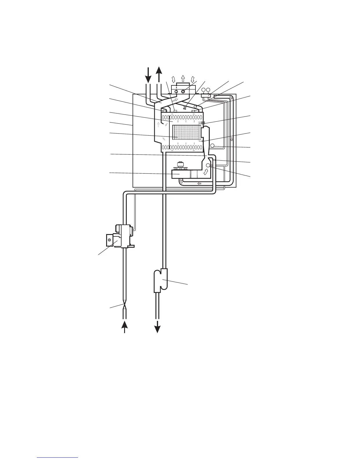
2.10 BOILER SCHEMATIC
Alpha CD13R, 18R, 24R - Technical Data
1 - Flue sampling point
2 - Flue thermostat
3 - Injector
4 - Gas valve
5 - Primary return temperature sensor
6 - Venturi
7 - Main burner
8 - Primary/condensing heat exchanger
9 - Room sealed chamber
10 - Fan
11 - Pressure differential test points
Fig. 2
12 - Flue hood
13 - Overheat thermostat
14 - Primary flow temperature sensor
15 - Drain point
16 - Ignition electrodes
17 - Flame sensing electrode
18 - Venturi negative point
19 - Venturi positive point
20 - Gas service cock
21 - Condensate trap
Gas Condensate
discharge
Primary
Heating
return
Primary
Heating
flow
20
4
1
-
-
+
+
10
21
11
2
14
16
3
12
8
7
17
18
6
19
9
15
13
5