24
1. Gain access behind the room sealed chamber panel as described in Section 8.1 and remove the combustion chamber
front assembly as described in Section 7.2.
2. Remove the screw securing the air inlet tube and remove.
3. Disconnect the fan wiring and remove the fan.
4. Remove the inlet and outlet flanges from the fan, fit them to the new fan and re-assemble in reverse order.
Ensure that the pressure tubes are connected correctly.
5. Re-assemble and test the boiler as described in Routine Servicing, Section 7.4 paragraphs 5 to 9.
8.7 IGNITION GENERATOR - Fig. 27
1. Gain access behind the room sealed chamber panel
as described in Section 8.1.
2. Disconnect all the wiring from the ignition generator.
3. Remove the two screws securing the generator and
remove.
4. Secure the new generator in position and re-
connect the wiring.
5. Re-assemble in reverse order.
8.8 TRANSFORMER - Fig. 27
1. Gain access behind the room sealed chamber
panel as described in Section 8.1.
2. Remove the screw securing the air inlet tube and
remove.
3. Remove the two screws securing the transformer
and remove the transformer.
4. Disconnect all of the wiring from the transformer
noting their position.
5. Fit the new transformer and re-assemble in
reverse order.
8.9 OVERHEAT THERMOSTAT - Fig. 27
1. Gain access behind the room sealed chamber panel as described in Section 8.1.
2. Disconnect the wiring from the overheat thermostat.
3. Unscrew and remove the overheat thermostat from the heat exchanger.
4. Fit the new overheat thermostat taking care not to cross thread it and re-assemble in reverse order.
8.10 FLUE THERMOSTAT - Fig. 27
1. Gain access behind the room sealed chamber panel as described in Section 8.1.
2. Remove the two screws securing the thermostat retaining bracket and remove the thermostat from the top rear of the heat
exchanger.
3. Disconnect the wiring.
4. Fit the new thermostat and re-assemble in reverse order.
8.11 GAS VALVE
1. The gas valve is located at the bottom of the boiler (see Fig. 13).
2. Disconnect the pressure tube from the gas valve.
3. Loosen the screw securing the electrical plug and remove the plug.
4. Disconnect the burner manifold union and the gas pipe union.
5. Remove the support bracket screws from beneath the boiler.
6. Lower the valve downwards and out of its location.
7. Unscrew the support bracket from the faulty valve and fit it to the new valve.
8. Fit the new assembly and re-assemble in reverse order.
9. Carry out a soundness test. Light the boiler and set the gas valve to the settings stated on the instruction sheet provided
with the new valve.
Alpha CD13R, 18R, 24R - Component Replacement
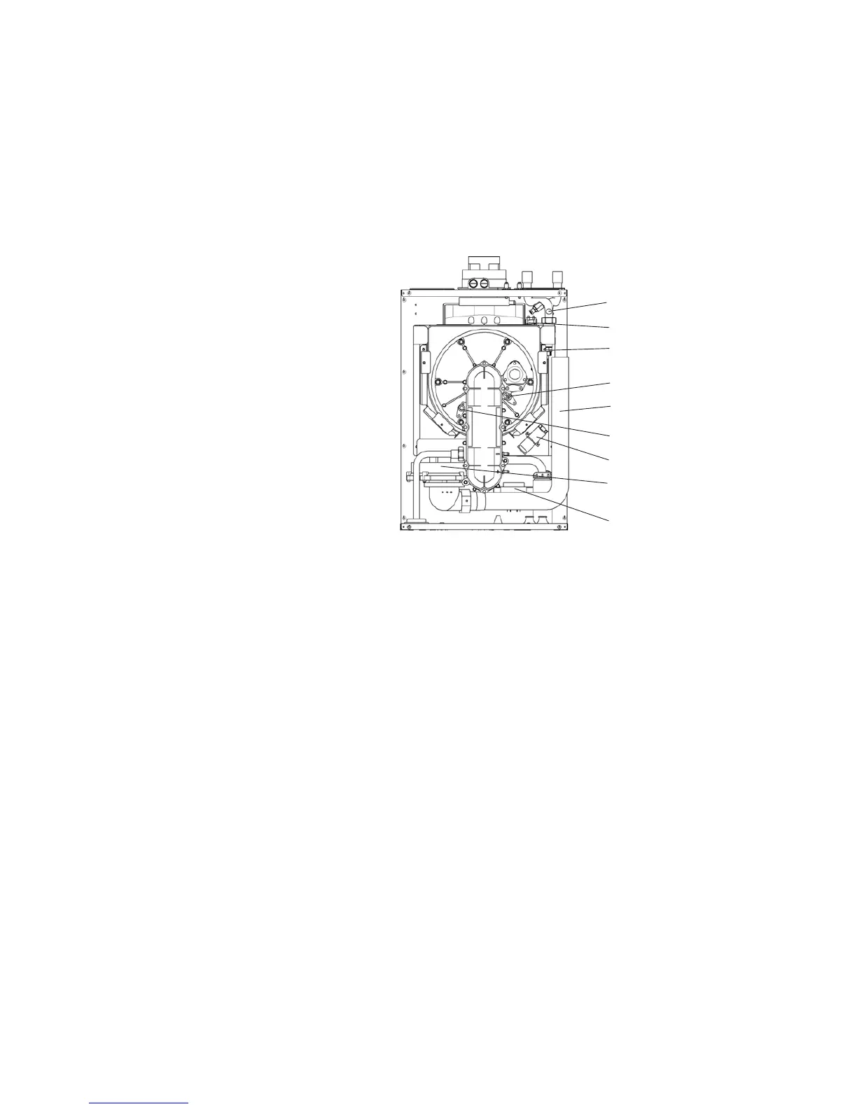
Fig. 27
Fan assembly
Flue thermostat
Primary flow and return
temperature sensors
Overheat thermostat
Ignition electrode
Flame sensing electrode
Ignition generator
Transformer
Air inlet tube