26
Alpha CD13R, 18R, 24R - Component Replacement
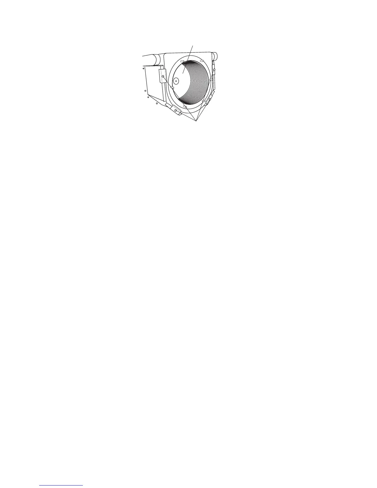
Fig. 29
8.17 COMBUSTION CHAMBER INSULATION
Gain access to the combustion chamber as described in Section 8.1.
Front insulation - see Fig. 26
1. Remove the electrodes from the combustion chamber front as described in Section 8.3.
2. Remove the four screws securing the burner.
3. Carefully remove the insulation.
Back insulation - see Fig. 29
1. Remove the combustion chamber front/burner assembly.
2. Remove the centre screw retaining the insulation.
3. Carefully remove the insulation, suction applied to the centre of the insulation will aid this.
Fit a new panel and re-assemble in reverse order.
Refill the system. (Refer to Commissioning, Section 5.1).
8.18 TEMPERATURE SENSORS - Refer to Fig. 27
Note that both sensors are the same.
1. Gain access as described in Section 8.1 and drain as described in Section 8.2.
2. Remove the screw securing the air inlet tube and remove.
3. The primary sensors are positioned on the right hand side of the heat exchanger (see Fig. 27), flow at the front and return
at the rear. Disconnect the wiring and unscrew the sensor using a 13 mm A/F socket spanner, (access to the return
sensor will be improved by removing the right side panel).
4. Re-assemble in reverse order with a new sensor and sealing washer.
Refill the system. (Refer to Commissioning, Section 5.1).
8.19 CONDENSATE TRAP - Fig. 13
1. Gain access behind the room sealed chamber as described in Section 8.1.
2. Disconnect the inlet and drain connection of the condensate trap.
3. Remove the fixing screw and lift the trap from its location.
4. Fill the new trap with water and fit it to the boiler and re-assemble in reverse order.
Back insulation panel
Four screws securing
heat exchanger