14
Alpha CD50 - Installation
4 INSTALLATION
4.1 UNPACKING
1. The boxes required when the boiler is installed with a horizontal flue are as follows:-
Box 1 Cased boiler fitted with water and gas valves, filling loop, union bends and washers
Mounting bracket plus screws and wall plugs
Pressure reducing valve and Tundish
Literature pack and Wall template
Box 2 CD Easy-Flue 500 mm or CD Easy-Flue 1000 mm. Both include 90° bend and horizontal flue terminal
Note: NOT required for vertical flue
Notes: a. All flues must be suitable for CD condensing boilers.
b. CD 750 mm and 1000 mm flue extensions are available, if required.
2. Unpack boiler and remove the loose items packs and mounting bracket.
Note: The boiler can be stood in an upright position, (to allow this, the union bends have been turned upwards so that they
do not protrude beneath the bottom - check this before standing the boiler upright).
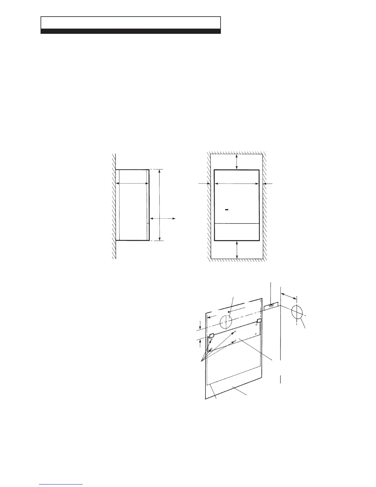
4.2 CLEARANCES REQUIRED - Fig. 12
Fig. 12
4.3 PREPARE THE WALL - Figs. 12, 13
1. Decide upon the position of the boiler taking into
account the clearances required for servicing and the
flue terminal position.
2. Tape the template to the wall (ensure it is level and the
right way up) and mark the position of the holes for the
boiler mounting bracket and bottom fixings. If rear exit
flue is used, mark the position of the hole for the flue.
3. Side exit flue - Continue the horizontal centre line of the
flue across the wall to the side wall, then along the side wall
235 mm (ensure the lines are horizontal). This will give the
position of the centre of the hole for the flue.
4. Cut the 110 mm diameter hole (or use a 107 mm core
drill) in the wall for the flue.
Notes: a. Ensure the hole is horizontal.
b. For internal fitting of the flue, using the flue
sealing collar supplied, cut a 130 mm dia. flue
hole using a 127 mm core drill.
5. Drill the fixing holes (10 mm dia.) to accept the No.10 plugs
supplied. Using the screws supplied, fit the mounting
bracket.
4.4 FIT THE BOILER - Refer to Fig. 13
1. Lift the boiler and locate it on the mounting bracket.
Fig. 13
420 mm
180 mm
Rear exit hole
110 mm dia.
Position of
110 mm hole
to be cut for
side exit
flue
Ensure line is level
Wall
mounting
bracket
Side
wall
235 mm
Boiler
outline
Template
Fixing
holes
140 mm
220 mm
10 mm
10 mm
600 mm
250 mm
450 mm
900 mm
Minimum
clearance
of 450 mm
from front
of boiler