5
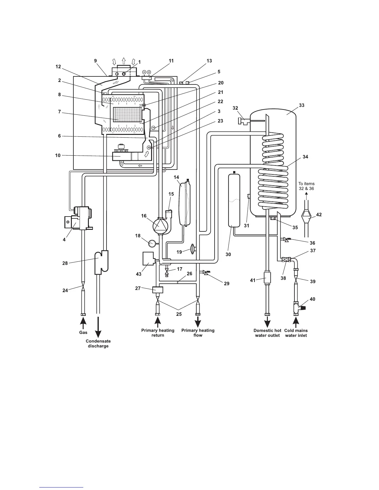
2.10 BOILER SCHEMATIC
Alpha CD50 - Technical Data
Fig. 2
1 Flue sampling point
2 Flue thermostat
3 Injector
4 Gas valve
5 Primary temperature sensor
6 Venturi
7 Main burner
8 Primary/condensing heat exchanger
9 Room sealed chamber
10 Fan
11 Pressure differential test points
12 Flue hood
13 Overheat thermostat
14 CH Expansion vessel
15 Automatic air vent
16 Pump
17 Drain point
18 Pressure gauge
19 Primary pressure switch
20 Ignition electrodes
21 Flame sensing electrode
22 Venturi negative point
23 Venturi positive point
24 Gas service cock
25 On/off valve (2 off)
26 Automatic by-pass
27 Cyclone separator
28 Condensate trap
29 CH Pressure Relief Valve
30 DHW Expansion Vessel
31 DHW Storage Temperature Sensor
32 DHW Temperature/Pressure Relief Valve
33 Storage Cylinder
34 Secondary Heat Exchanger
35 DHW Drain Point
36 DHW Expansion Relief Valve
37 Mains Inlet Filter
38 Check Valve
39 Mains Inlet Valve
40 Pressure Reducing Valve with Filter
41 Automatic Flow Regulator
42 Tundish
43 Diverter Valve