3
7 minutes
3 minutes
5 minutes
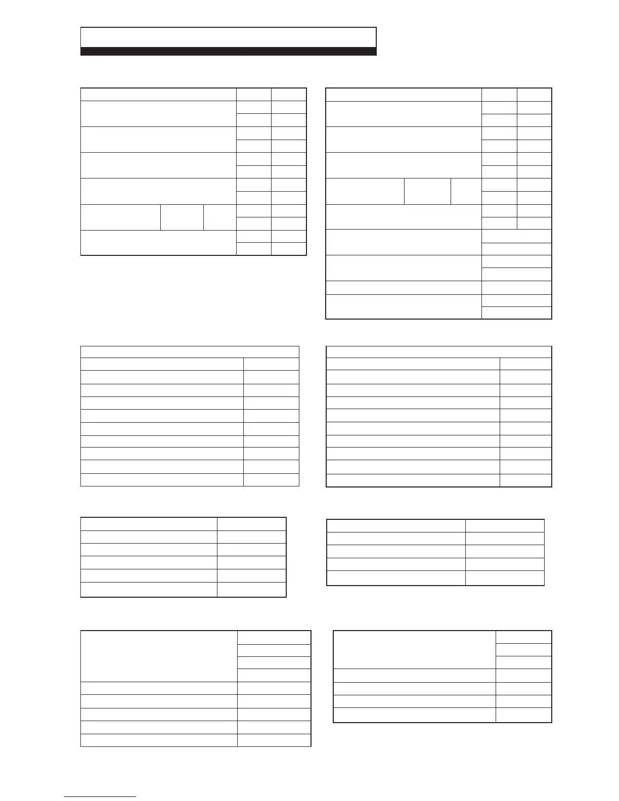
2.1 PERFORMANCE - NATURAL GAS (CAT: 2H-G20-20 mbar)
2 TECHNICAL DATA
Alpha CD50 - Technical Data
MAX.
31.0
105 770
28.0
95 230
29.7
101 430
27.6
94 130
2.91
1.16
2.95
104.1
MIN.
7.4
25 360
6.6
22 830
7.0
23 980
6.5
21 500
0.27
0.11
0.71
25.1
Room sealed
chamber panel
fitted
Central Heating
Heat Input (H
s
)kW
(Gross) Btu/h
Heat Input (H
i
)kW
(Net) Btu/h
Heat Output (H
s
condensing) kW
(50°C/30°C) Btu/h
Heat Output (H
i
non-condensing) kW
(80°C/60°C) Btu/h
Differential Burner mbar
Pressure in wg
Gas Rate m³/h
ft³/h
Central Heating (Sealed System)
Max. Working System Pressure
Min. System Pressure
Max. System temperature
Pressure Relief Valve Setting
Expansion Vessel Size (pre-charge press.)
Flow Connection
Return Connection
Relief Valve Connection
Recommended System Pressure (cold)
CH Water Temp. (Approx. max.)
2.5 bar
0.5 bar
82°C
3 bar (44 PSI)
8 L at 0.8 bar
22 mm
22 mm
15 mm
1.0 bar
82°C (180°F)
2.2 SYSTEM
Burner
Main Heat Exchanger
DHW Storage Cylinder
Main Burner Injector
Flue - Outer Duct
Flue - Inner Duct
Stainless steel
Stainless steel
Stainless Steel
6.6 mm
White
Plastic
2.3 COMPONENTS 2.4 ELECTRICAL
Supply
External Fuse
Power Consumption
Internal Fuse
Electrode Spark Gap
230/240 V ~ 50 Hz
3 A
140 W
F2 A
3 - 4 mm
MIN.
7.4
25 360
6.6
22 830
6.3
21 500
0.27
0.11
0.71
25.1
1.0
0.22
5
41
Domestic Hot Water
Heat Input (H
s
)kW
(Gross) Btu/h
Heat Input (H
i
)kW
(Net) Btu/h
Output to Water (H
s
)kW
(modulating) Btu/h
Differential Burner mbar
Pressure in wg
Gas Rate m³/h
ft³/h
Flow Rate L/min
G.P.M.
Outlet Water Temp. (Approx.) °C
°F
Time to raise water store by 50°C
Reheat time for 70% of store
(boiler ON)
(boiler OFF)
5.5 bar
12 bar
0.1 bar
15 mm
15 mm
52 L
4 L at 2.5 bar
2.5 bar
90°C/7 bar
6 bar
Domestic Hot Water
Max. Hot Water Working Pressure
Max. Mains Inlet Pressure (inlet of pressure reducing valve)
Min. Mains Water Pressure
Mains Inlet Connection
DHW Outlet Connection
DHW Water Storage
Expansion Vessel Size (pre-charge press.)
Pressure Reducing Valve Setting
Temperature and Pressure Relief Valve
Expansion Relief Valve Setting
900 mm
600 mm
450 mm
22 mm
3.2 L
100 mm
60 mm
Case Dimensions Height
Width
Depth
Gas Connection
Primary Water Content
Air Duct Diameter
Flue Duct Diameter
2.6 GENERAL
Min. Clearances for Servicing Top
(from casing) Bottom
Sides
Front
Flue Terminal Size
Flue Terminal Protruding
Hole Size Required For Flue Assy.
Lift Weight
Weight Full and Operational
2.5 INSTALLATION
220 mm
250 mm
10 mm
450 mm
100 mm Dia.
100 mm
110 mm Dia.
70 kg
130 kg
Room sealed
chamber panel
fitted
MAX.
36.1
123 190
32.6
110 910
32.0
109 200
3.70
1.48
3.44
121.4
18.0
4.0
65
149