17
Alpha InTec² 26E, 30CE and 35CE - Installation
4.4 FIT THE BOILER - Refer to Figs. 4.2 and 4.3
Lift the boiler and locate it on the mounting bracket - the boiler should be lifted
by two persons.
Note: When handling or lifting always use safe techniques - keep your back
straight, bend your knees, don't twist - move your feet, avoid bending forwards
and sideways and keep the load as close to your body as possible.
Where possible transport the boiler using a sack truck or other suitable trolley.
Always grip the boiler firmly, and before lifting feel where the weight is concentrated
to establish the centre of gravity, repositioning yourself as necessary.
4.5 CONNECT THE PIPEWORK - Fig. 4.4
1. Thoroughly flush out all the water pipework. Refer to Section 3.9.
2. Fit the valves to the boiler connections as shown in Fig. 4.4 - note the
colours of the operating levers.
When fitting the filling loop keep it assembled (as supplied) and adjust
the width (on the sliding connection) to match the distance between the
cold mains inlet and heating return valves. Tighten the nuts, keeping the
valves aligned, in order to allow the connection pipe to slide.
3. Connect the system pipework to the union fittings on the valves just fitted.
Note: When soldering bends, ensure they are not connected to the valves, otherwise the internal seals may be
damaged.
One metre of copper pipe must be fitted to the boiler before connecting to any plastic pipework.
4. Connect the flexible condensate pipe to the rubber connector as shown in Fig. 4.4. Using the adaptor supplied, connect
the flexible pipe to the condensate drain.
Ensure that the condensate discharge pipe is as required in Section 3.10.
5. Ensure that all the valves are closed (operating lever at right angle to valve) and do not turn on the water or gas supplies
at this stage.
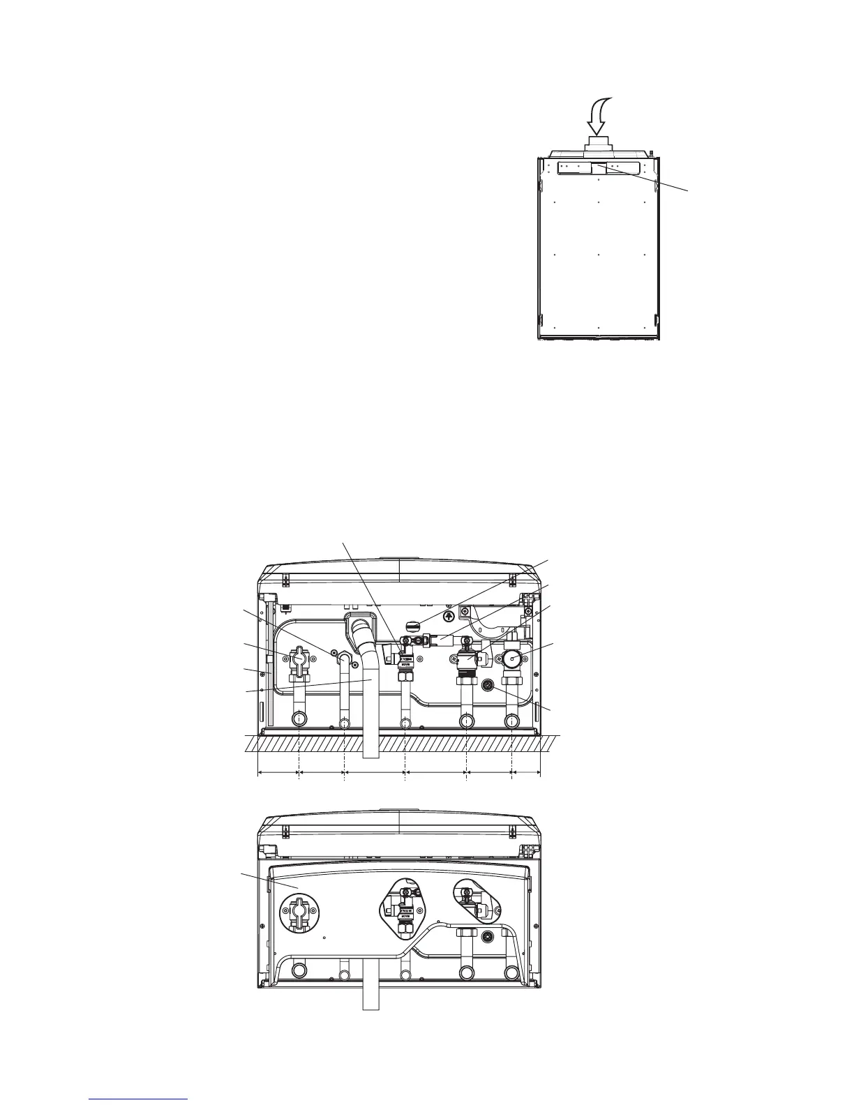
Fig. 4.3 - rear of boiler
Location for
wall mounting
bracket on
rear of boiler
Pour water into flue duct
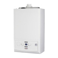
Fig. 4.4
A - Gas inlet - Yellow (22 mm)
B - DHW outlet elbow (15 mm)
C - Cold water inlet - Black (15 mm)
D - Heating return - (22 mm)
E - Heating flow - (22 mm)
Hot water outlet
Condensate discharge pipe
Heating drain point
Gas service cock (yellow)
Heating return valve
Safety valve operation indicator
Cold water inlet (black), filter and restrictor
Heating flow valve
Electrical connection
A B C
D
E
65 70 457095 95
Filling loop assembly
Bottom cover plate