42
Fig. 7.2
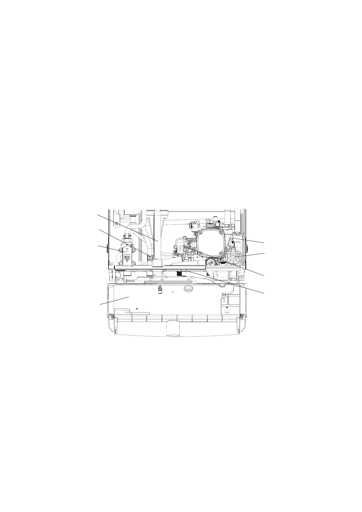
Alpha InTec² 25XE and 28XE - Component Replacement
7.11 CONDENSATE TRAP - Figs. 6.7 and 7.2
Gain access as described in Section 7.1.
Note: Before removing the trap, ensure that the water from the trap can be contained to avoid spillage.
1. Pull the flue drain hose off the top of the condense trap, cut the cable tie and pull the rubber condense hose adapter out
of the bottom of the boiler.
The cable tie is only to secure the adaptor during transit and installation, it is not required after removal.
2. Remove the trap fixing screw from the bottom of the boiler and turn the trap to the left to disconnect it from the
expansion valve outlet pipe.
3. Rotate the trap in a slight backwards motion to disconnect it from the flue manifold, being careful not to spill any
condense water, remove the trap from the boiler.
4. It is important to clean the trap every time the trap is removed to flush out any deposits from the collection bowl.
Note: Partially fill the trap before replacing.
7.12 DHW FLOW SWITCH - Fig. 7.2
1. Gain access behind the front casing as described in Section 7.1.
2. Isolate the mains water supply and open all hot taps to drain any water from the boiler.
3. Disconnect the wires from the switch.
4. Undo the union nut and remove the fixing screw from the bottom of the switch.
5. Remove the two 4 mm cap head screws securing the top and lift out the switch.
6. Fit the new switch and re-assemble in reverse order.
7.13 PRIMARY HEAT EXCHANGER - Fig. 6.7
Gain access and drain the boiler heating circuit as described in Sections 7.1 and 7.2.
1. Remove the condensate trap assembly as described in Section 7.11.
2. Remove the electrode as described in Section 7.3 and check its condition.
3. Remove the three screws securing the fan air/gas manifold and remove the two spring clips at either end of the gas
pipe, removing the pipe and manifold together.
4. Unscrew the flue sampling point cap and remove the complete fitting from the top of the case.
5. Disconnect the flue sensor wires and remove the lower retaining screw on the flue manifold assembly.
6. Pull down the flue manifold assembly and withdraw the complete assembly.
7. Disconnect the primary sensor and fan wires.
8. Unlatch the two clips 'A' in Fig. 6.5 securing the fan and burner cover and remove the complete assembly.
9. Disconnect the earth wire from the burner and lift the burner out of the heat exchanger.
10. Remove the retaining clips from the flow and return pipes at the heat eaxchanger and water manifold and remove the
pipes.
11. Remove the two screws securing the bottom rear of the heat eaxchanger to the condensate sump.
DHW Flow switch
Diverter valve motor
and assembly
Flow switch bottom
fixing screw
Retaining clip
DHW temperature sensor
Condensate trap
Gas valve
PCB cover