EasyManua.ls Logo

Alpine 3552S User Manual

Alpine 3552S
34 pages
To Next Page IconTo Next Page
Page #1 background imageLoading...
Page #1 background image
SERVICE
MANUAL
ZILPIN
4/3/2
Channel
Power
Amplifier
@
This
service
manual
is
based
on
Basic
Model
3552.
@
This
service
manual
only
contains
parts
of
items
to
be
modified.
Therefore
please
refer
to
service
manual
3552
(68P20604W02)
for
the
unmentioned
parts.
ony
osy
fa
FF
Sees
wager
ST
Le
or
we
fined
vamance
Nar
So
vant
Fink
oF
ur
tr
MONO)
ST
Le
WNPUT
MODE
FUTER
eh
conta,
PUTER
twPUT
MODE
CHANEL
(2.714)
Question and Answer IconNeed help?

Do you have a question about the Alpine 3552S and is the answer not in the manual?

Alpine 3552S Specifications

General IconGeneral
Channels2
THD at RMS Power0.08%
Frequency Response10Hz
Input Sensitivity0.2 - 4.0V
Crossover Frequency50Hz
Bass Boost12dB
CrossoverLP/HP

Summary

Parts Layout on P.C.Boards and Wiring Diagram

Schematic Diagram

IC's and Transistors Voltage Values

Cabinet Assembly Parts List

Exploded View (Cabinet)

Electrical Parts List

Specifications

Features

Operational Modes and Settings

Explains different channel configurations and input signal modes.

Circuitry and Performance Enhancements

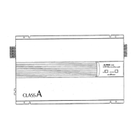
Details advanced circuit designs for improved audio performance and stability.

User Interface, Build, and Protection

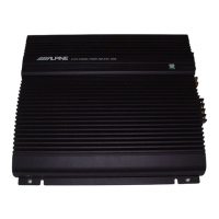
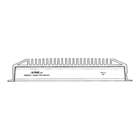
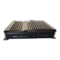
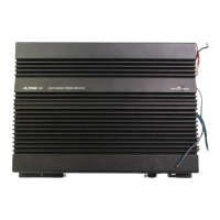
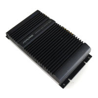
Describes interface elements, build quality, and protection features.

Switches And Terminals

Front Panel Controls

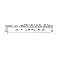
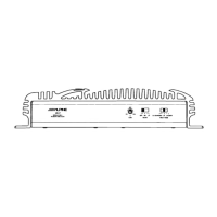
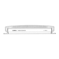
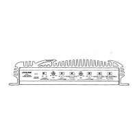
Identifies and describes the front panel switches and controls.

Rear Panel Connections

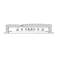
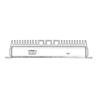
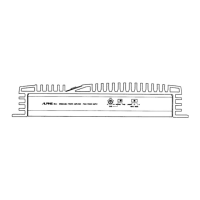
Identifies and describes the rear panel terminals and connectors.

Switch Settings

Input Mode and Sensitivity

Configuring input modes and sensitivity for various audio sources.

Crossover and Gain Adjustment

Setting the crossover frequency and adjusting input gain levels.

Status Monitor Indicator

Understanding the status monitor light for operational feedback.

Characteristic Curves

Connections

Speaker Output Wiring

Guidance on connecting speakers for stereo and bridged modes.

Power and Ground Wiring

Instructions for secure ground and battery connections.

Signal Input and Remote Turn-On

Connecting the remote turn-on signal and RCA line inputs.

Disassembly Instructions

Bottom Cover Removal

Procedure for removing the bottom cover of the amplifier.

Main Board Removal

Steps for removing the main amplifier printed circuit board.

Block Diagram

Packing Method View

Packing Assembly Parts List

Related product manuals