Do you have a question about the Alpine 3541 and is the answer not in the manual?
Explains the amplifier's flexibility in 2-channel stereo or bridged mono configurations.
Details the Duo-Beta circuitry for error correction, minimizing distortion and stabilizing the amplifier.
Highlights the absence of current limiters for improved transient response and sonic quality.
Describes Alpine's proprietary Signal Transit for Accurate Response circuitry for improved sonic properties.
Details the use of an accessory for connecting to head units without pre-amp outputs.
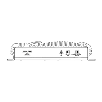
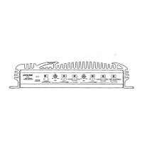
Describes the switch for selecting input signal type (Stereo, L(MONO), L+R).
Details the power supply for excellent output throughout the audio bandwidth with soft clipping.
Highlights the use of glass-epoxy boards and high current bus-bars for durability.
Explains discrete output circuitry for reliability, performance, and high current capability.
Describes the adjustable gain control for matching input sensitivity and compensating for speaker efficiencies.
Mentions gold-plated RCA connectors for accurate signal transmission and corrosion resistance.
Notes gold-plated speaker output and power connectors for high-definition power transfer.
Highlights the use of high-performance, low-noise, audiophile-quality components.
Describes filtering for low RFI and immunity to system noises.
Details the settings for stereo, mono, and summed mono input modes.
Explains settings for fixed sensitivity (Alpine products) and variable sensitivity (non-Alpine products).
Guides on adjusting input gain for optimal volume without distortion.
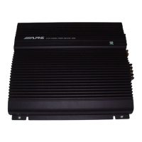
Describes the green indicator light that shows when the power is on.
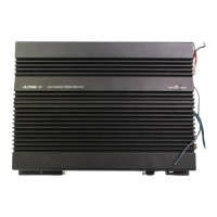
Advises on correct speaker connections, phasing, and polarity.
Details securing the ground lead to a clean chassis point for proper grounding.
Guides connecting the battery lead to the positive terminal with a fuse for protection.
Explains connecting the remote turn-on lead to the head unit.
Details connecting line-out leads from the head unit via RCA patch cords.
Describes using the 4311 accessory for head units without pre-amp outputs.
Warns that improper wiring can damage the vehicle's electrical system or the amplifier.
Emphasizes connecting the battery lead last after all other connections are made.
Stresses the importance of clean, secure connections due to high power output.
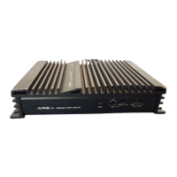
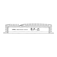
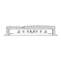
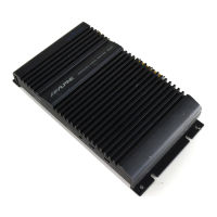
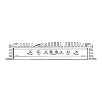
Advises mounting the amplifier for free air circulation and heat dissipation.
Instructs to use only fuses of the same amperage to prevent component damage.
Details removing the bottom cover by unscrewing and pulling it off.
Explains removing the main circuit board after the bottom cover is off.
Displays the component layout and wiring for the main amplifier circuit board.
Shows the component layout and wiring for the output connector circuit board.
Details the component layout and wiring for the RCA input connector circuit board.
Shows the component layout for the LED indicator circuit board.
Provides pin-by-pin voltage values for the IC101 integrated circuit.
Lists voltage readings for IC102 and IC202 integrated circuits.
Details the pin voltage values for the IC301 integrated circuit.
Lists voltage values for various transistors used in the amplifier.
Provides voltage values for the diodes used in the amplifier.
Lists voltage values for various capacitors in the circuit.
Contains notes on measurement conditions, reference points, and meter usage.
Defines abbreviations for electrical components like resistors, capacitors, and transistors.
Lists resistors, transistors, diodes, and capacitors for the main amplifier circuit board.
Details capacitors used in the amplifier, including their type and value.
Lists transformer and coil components with their part numbers and specifications.
Details the slide switch used for mode selection.
Lists various resistors with their part numbers, type, and resistance values.
Lists miscellaneous components like diodes, terminals, fuses, ICs, LEDs, and transistors.
Lists potentiometer (volume) controls with their part numbers and resistance values.
Lists components for the output connector circuit board.
Details capacitors used on the output connector circuit board.