Do you have a question about the Alpine 3527 and is the answer not in the manual?
Details on using the 3527 as a 4, 3, or 2 channel amplifier, including bridged configurations and MultiMode capabilities.
Description of the built-in 80 Hz, 18 dB/octave electronic crossover for setting up speaker outputs.
Explanation of Alpine's proprietary Duo-Beta feedback for advanced audio performance and stability.
Information on the amplifier's ability to power 6-channel or 5-channel systems with satellites and subwoofers.
Highlights the absence of current limiters for improved transient response and sonic quality.
Details on connecting high or standard power head units without pre-amp outputs using speaker level inputs.
Explains the Signal Transit for Accurate Response topology for improved sonic properties.
Describes the switch for selecting input signals like Stereo, Mono Single Input, or Summed Mono Input.
Information on the power supply providing excellent output and transient response with soft clipping.
Details on circuitry providing reliability, performance, and high current capability.
Explanation of adjustable gain controls for different audio sections (CH1/2 and CH3/4).
Highlights the benefits of gold-plated connectors for accurate signal transmission and low loss.
Notes the use of audiophile quality active and passive components for optimal performance.
Explains capacitive/inductive input/output filtering for RFI immunity and noise reduction.
Details on the input stage providing excellent stability and low noise.
Describes the LED that visually confirms the unit is operational.
Addresses issues with the power indicator not turning on, checking head unit and ground connections.
Troubleshoots lack of audio output, covering remote-on wire, protection circuits, audio cables, and gain settings.
Diagnoses causes like overheating, shorts, poor connections, and explains how to reset protection circuits.
Provides solutions for engine noise in the audio, covering ground loops and component noise suppression.
Specifies the total power output of the amplifier at 14.4V.
Lists RMS power outputs for 4-channel, 3-channel, and 2-channel modes with THD percentages.
Provides the frequency range the amplifier can reproduce.
States the dBA rating for noise level relative to rated power.
Indicates the slew factor, a measure of transient response.
Defines the range for line and speaker input sensitivity settings.
Specifies the impedance for line and speaker inputs.
Lists the compatible speaker impedances for stereo and bridged modes.
Details the frequency (80 Hz) and slope (18 dB/octave) of the crossover.
Specifies the voltage (11-16V DC) and ground type required.
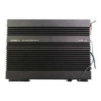
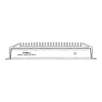
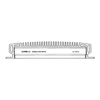
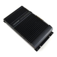
Provides the physical dimensions of the 3527 amplifier.
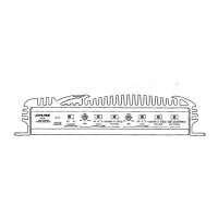
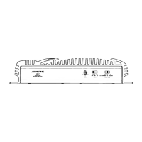
Adjusts input sensitivity for channels 1 and 2, with detent for Alpine standard.
An LED that visually confirms the unit is operating.
Configures the crossover for CH1/CH2 to OFF, LP (low-pass), or HP (high-pass).
Selects input routing for CH1/CH2: Stereo, Mono, or Summed Mono.
Configures the crossover for CH3/CH4 to OFF, LP (low-pass), or HP (high-pass).
Selects input routing for CH3/CH4: Stereo, Mono, or Summed Mono.
Adjusts input sensitivity for channels 3 and 4, with detent for Alpine standard.
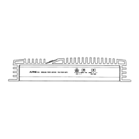
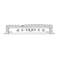
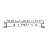
Connects RCA output from head units or signal processors to the amplifier.
Connects speaker outputs from head units without pre-amp outputs.
Terminals for connecting speakers to channels 1 and 2.
Terminals for connecting speakers to channels 3 and 4.
Location of the 25A fuse for protecting the amplifier.
Terminals for connecting power, remote turn-on, and ground leads.
Key precautions before starting wiring, including disconnecting battery and avoiding chassis grounds.
Instructions on selecting a location, marking, drilling, and securing the unit.
Guidance on routing cables, using quality RCA cables, and proper power/ground connections.
Details on connecting the remote-on lead, especially when head unit outputs are limited.
Guides on setting input modes, filter switches, and output configurations.
Instructions for connecting and setting up the amplifier for 4-channel output.
Wiring diagram for 4-channel operation with high-pass satellites or full-range speakers.
Wiring diagram for 3-channel operation with satellites and a mono subwoofer.
Wiring for 2-channel operation with high-pass satellites or full-range speakers.
Wiring for 2-channel operation with non-fading subwoofers.
Diagram and explanation for MultiMode setups, combining satellite and subwoofer outputs.
| Channels | 2 |
|---|---|
| Frequency Response | 10Hz - 50kHz |
| THD | 0.08% |
| Input Sensitivity | 200mV - 4V |
| Weight | 2.2kg |