Do you have a question about the Alpine 3544 and is the answer not in the manual?
Details power output, input sensitivity, frequency response, etc. for 4-ohm stereo.
Details power output and current drain for 2-ohm stereo operation.
Details power output and current drain for 4-ohm BTL mono operation.
Covers fuse, power source, component count, dimensions, and weight.
Explains stereo and bridged operation modes and power outputs.
Describes the function of the status indicator light for operation and protection.
Details Duo-Beta, No Current Limiting, and S.T.A.R. circuit features.
Details using an accessory for head units without preamp outputs.
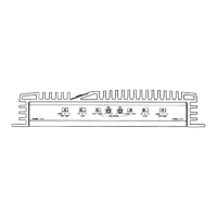
Details the "ST", "L (MONO)", and "L+R" positions for input signal selection.
Explains "FIXED" and "VARIABLE" positions for input sensitivity adjustment.
Explains how to adjust the input gain control for optimal volume.
Explains the green and orange status indicator lights and their meanings.
Graph showing Total Harmonic Distortion versus output power at 1kHz/4 ohms.
Graph showing frequency response from 20Hz to 100kHz at 1W/4 ohms.
Details the connection of RCA input jacks and speaker output terminals.
Explains connections for battery lead, ground lead, and remote turn-on lead.
Details using speaker outputs with an interface for head units lacking preamp outputs.
Warns about improper wiring causing damage and emphasizes following instructions.
States the battery lead connection should be the last step after all others are made.
Stresses clean and secured connections for high-power output to prevent damage.
Advises mounting the amplifier for free air circulation and heat dissipation.
Emphasizes using fuses of the same amperage to prevent component damage.
Details removing the bottom cover using specific screws.
Outlines steps for removing the main PC board, including screws and components.
Details connecting a meter and adjusting VR801 for the correct power supply voltage.
Explains connecting a meter and adjusting VR501/VR502 for the correct idling voltage.
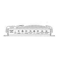
Shows RCA input, speaker terminals, and power/remote connectors.
Depicts DC-DC converter, muting, remote control, and protection circuits.
Illustrates buffer, amplifier stages, and driver circuits within the block diagram.
Shows component placement for the RCA input circuit board.
Shows component placement for the Speaker Output circuit board.
Details component placement on the main printed circuit board.
Shows the left portion of the schematic diagram, including input and driver stages.
Lists voltage values for IC501, IC502, IC201, IC202 under secondary ground reference.
Lists voltage values for IC503, IC801, IC802 under primary ground reference.
Provides voltage measurements for various transistors under primary and secondary ground references.
Lists part numbers and descriptions for various ICs used in the amplifier.
Lists part numbers and descriptions for transistors used in the amplifier.
Lists part numbers and descriptions for diodes used in the amplifier.
Lists part numbers and descriptions for capacitors used in the amplifier.
Lists part numbers and descriptions for capacitors and coils.
Lists part numbers and descriptions for thermistors, switches, and resistors.
Lists part numbers and descriptions for variable resistors (potentiometers).
Lists part numbers and descriptions for miscellaneous items like fuses and connectors.
Illustrates the method used for packing the amplifier for shipment.
Lists the parts included in the packing assembly.
Shows the pinout and identification for the µPC4570C integrated circuit.
Shows the pinout and identification for the µPC1298V integrated circuit.
Shows the pinout and identification for the 82675F02 integrated circuit.
Shows lead identifications for µPC494C and P52401 integrated circuits.
Displays lead identifications for various transistors like 2SD1996, 2SC3423, 2SA1358, etc.
Shows lead identifications for transistors 2SB1076M, 2SC4024, 2SD1065, etc.
| Power Output (RMS) | 50W x 4 |
|---|---|
| RMS Power at 4 Ohms | 50W x 4 |
| RMS Power at 2 Ohms | 75W x 4 |
| Bridged RMS Power at 4 Ohms | 150W x 2 |
| Frequency Response | 10Hz - 50kHz |
| Input Sensitivity | 200mV - 4V |