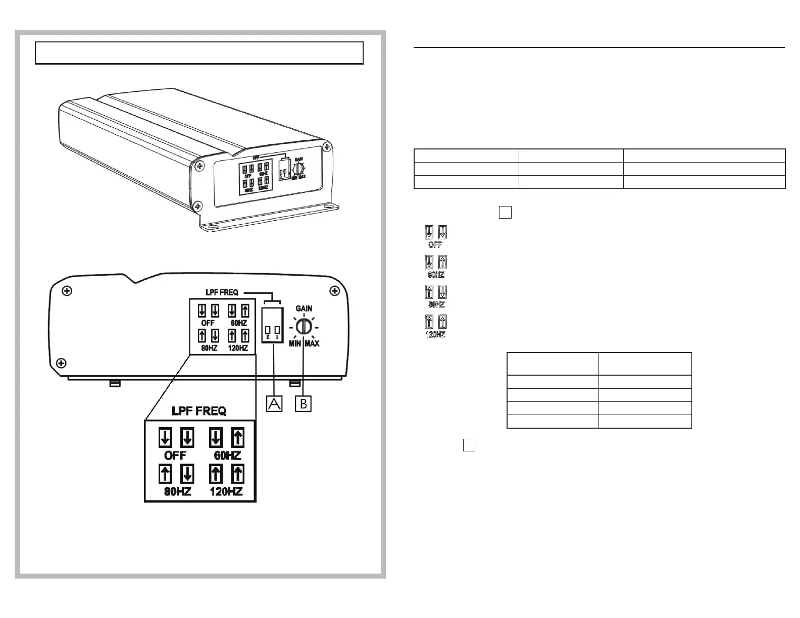
SWITCH SETTINGS (Fig. 2)
9 Gain Setting
Set the KTA-200M input gain to the minimum position. Using a dynamic CD as a source,
increase the head unit volume until the output distorts. Then, reduce the volume 1 step (or
until the output is no longer distorted).
Now, increase the amplier gain until the sound from the subwoofer becomes distorted. Reduce
the gain slightly so the sound is no longer distorted to achieve the optimum gain setting.
0 Low Pass Filter Selector Switches
Switch number 1 and 2 are for low pass lter settings. Default setting for low pass lter is off.
Control section Switch number Function
A 1 & 2 Filter conguration
B N/A Gain control
FILTER Conguration
A
:
Filter off position: Switch 2 and 1 down.
Filter is set for 60Hz low pass; switch 2 down and 1 is up.
Filter is set for 80Hz low pass; switch 2 up and 1 is down.
Filter is set for 120Hz low pass; switch 2 up and 1 is up.
Function
Switch number &
position
LPF off 2 down & 1 down
LPF 60Hz 2 down & 1 up
LPF 80Hz 2 up & 1 down
LPF 120Hz 2 up & 1 up
Gain control
B
:
This control is for input voltage sensitivity adjustment to allow use with various signal sources
with RCA level subwoofer outputs.
1. Full rated output is obtained with the appropriate settings.
2. Distortion can be had when the gain control is set incorrectly.
Fig. 2
KTA-200M Left side panel/Panneau de gauche/Panel izquierdo