Fig.
7
c)
Set to the "OFF" position
when
the amplifier
will be used for driving full-range speakers.
The full frequency bandwidth will be
output to the speakers with
no
high
or
low
frequency attenuation.
b) Set to the "HP" position
when
the amplifier
is used to drive a tweeter/midrange system.
The
frequencies below the crossover point
will be attenuated
at12
dB/octave.
FILTER
lro
---',
<-
OFF
HP
LP
FILTER
rn
---',,-
OFF
HP
LP
*
OFF
HP
LP
• Cautions
on
Power Wire
connections
The power wire
cannot
be connected until its end has
been
stripped. Below explains how to connect the stripped end
of
the
power
wire.
Notes:
Use the .mpplied he.wgol/
screws/or
this cO/lnection. It
i~'
highly
recommended
/hat
lhi.~
be
carried
ow
by
the dealer.
Ifyuu
make
this cOf/Iln-tion
yourself
ensure the cOl/nection is
correct
by
following the
i/lSlrucrion.~
below
careflllly
Be silre
to
lise the .\'lIpplied hexllgmr
screw~"for
thi.l·
cO/lflection.
For safety
ret/SOIlS.
COlll/ect the
bauery
wire last.
To
!Jrevetlt disCOllllectioll
of
tile leads
or
droppil/g
of
the
UIl;t,
do
not
('(jrry Ihe
u1Iit
by
the wire.
Be SlIre to
mid
afuse
as
dose
as
pos.\'ihle to the baltery. Make
sure to use
aflue
oj/he
correN
ra/ingfor
the
power
wire.
1.
Check the wire gauge.
Notes:
Only
lue
4AWG·6AWGI13
mm"_21 mm" (the wire
gallge)for
tllis cOlll/ection
•
If
in doubt. CO/lsult
your
(Iealer
or
Customer
Supporr
reglln/ing correct wire gallge to use.
2.
Strip back between 7-10
mm
(9/32--3/8")
of
the power
wire's insulation to expose the conductor.
Notes:
If
Ihe length
of
Ihe
exposed
com/uctor
i.\·
100
shorr. a IJoor
COIlIlectioll lIIay
occur
cllusing operatiollfllill/!"C
or
SOI/IU/
illterruptiof!.
COl/versely.
if
the
exposed
conductor
is too
/0I1R.
all
electrical
~'}lOrt-circ/(it
/lWV
OCCIII:
3.
Loosen the unit's wire terminal hexagon screws, and insert
the exposed conductor into the terminal and finally tighten
to secure the connection.
4.
Verify that the power wire is connected securely.
• Cautions
on
speaker wire
connections
When
you connect the speaker wire to the unit. you need to
insert the speaker wire into the speaker connector. Below
explains how to
insert
the speaker wire into the speaker
connector.
1.
Check
the wire gauge.
Notes:
Tlte
ami/able
S!Jellker wire glU/ge/or
thi.~
IIl1it
is
,sAIVG-
16AWGI8
mm
I
-
13 mm".
•
If
in doubt.
consult
your
l/eliler regardillK
correct
wire gallge
to /lse.
2.
Strip back between 7-10
mm
(9/32--3/8")
of
the wire's
insulation to expose the conductor.
Notes:
If
the lel/glh
of
the
exposed
COfl{/uctor is
too
.~hor/.
a
poor
COl/nection
may
occur
callsing operatiol/fllilure
or
sound
interruptioll.
Conwrse/y.
iflhe
eXlwsed l'onductor is too
101/g.
WI
electrical
~'hort-circ/(it
/lUlV
OCCIlr.
3 Loosen fully the speaker plug's 2 hexagon screws using
the hexagon wrench (small. supplied).
4.
Insert fully the exposed conductor
of
the speaker wire into
the wire terminal hole. Refer to Fig.
8.
Note:
l/lsert the spetlker wire observi/lg tile +1- illl/iullio/ls
OIl
the
speaker
COllllec/or. Illsert the positive
.~IJellker
It-'ire
into the
positive
speaker
termi/wl,
and
rhe negative .I'pulker wire into
the lIeglltive .\peaker termillal.
5.
Tighten the 2 hexagon screws using the hexagon wrench
(small, supplied).
CD,
m
Crossover
Mode
Selector
Switch
FILTER
a)
Set
to the "LP" position when the amplifier is
used to drive a subwoofer.
The
frequencies
above the crossover point will be attenuated
at
12 dB/octave.
SWITCH SETTINGS (Fig. 9)
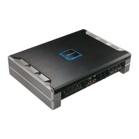
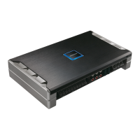
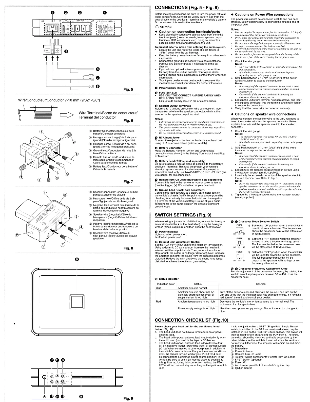
CONNECTIONS (Fig. 5 - Fig. 8)
When
making adjustments 10·15 below, remove the hexagon
screw (indicated by
* in the illustration) using the hexagon
wrench (small. supplied), and then open the control cover.
o
Power
Indicator
Lights up
when
power is on.
Is off when
power
is off.
0.
G)lnput
Gain
Adjustment
Control
Set the PDX4F6/F4 input gain to the minimum (4V) position.
Using a dynamic CD as a source, increase the head unit
volume until the output distorts. Then, reduce the volume 1
step (or until the output is
no
longer distorted). Now, increase
the amplifier gain until the sound from the speakers becomes
distorted. Reduce the gain slightly so the sound is
no
longer
distorted to achieve the optimum gain setting.
Cit
Battery
Lead
(Yellow,
sold
separately)
Be sure to add a a fuse
as
close as possible to the battery's
positive
(+) terminal. This fuse will protect your vehicle's
electrical system in case
of
a short circuit. If you need to
extend this lead, only use
4AWG-6AWG/13
mm
2
-
21
mm
2
(the
wire gauge) for this connection.
8
Remote
Turn-On
Lead
(BluelWhite.
sold
separately)
Connect this lead to the remote turn-on
or
power
antenna
(positive trigger. (+) 12V only) lead
of
your
head unit.
e
Ground
Lead
(Black,
sold
separately)
Connect this lead securely to a clean, bare metal spot on
the vehicle's chassis. Verify this point to be a true ground by
checking for continuity between that point and the negative
(-)
terminal
of
the vehicle's battery.
Ground
all
your
audio
components to the same point on the chassis to prevent
ground loops.
Before making connections, be sure to turn the
power
off to all
audio components. Connect the yellow battery lead from the
amp directly to the positive (+) terminal of the vehicle's battery.
Do not connect this lead to the fuse block.
&
CAUTION
• Caution
on
connection
terminals/parts
Keep electrically conductive objects away from the unit's
terminals/parts (power terminals, fuses, speaker output
terminals,
RCA
connectors, etc.). Doing so prevents a
possible short circuit and
damage
to the unit.
To
prevent
external
noise
from
entering
the
audio
system.
• Locate the unit and route the
leads
at
least 10
cm
(3-
15/16") away from the
car
harness.
Keep the battery
power
leads as far away from other leads
as possible.
Connect the ground lead securely to a bare metal spot
(remove any paint
or
grease if necessary)
of
the
car
chassis.
If you add an optional noise suppressor, connect it as
far away from the unit as possible. Your Alpine
dealer
carries various noise suppressors, contact them for
further
information.
Your Alpine dealer knows best about noise prevention
measures so consult
your
dealer for further information.
o
Power
Supply
Terminal
e
Fuse
(30A
x
2)
USE ONLY
THE
CORRECT
AMPERE
RATING
WHEN
REPLACING FUSES.
Failure to
do
so may result in fire
or
electric shock.
e
Speaker
Output
Terminals
Referring to "Cautions on speaker wire
connections~.
insert
the speaker wire into the speaker connector, which is then
inserted in the speaker output terminal.
Notes:
Fully
ill~'ert
the
speaker
COl/llector
10
al'oid
poor
connection.
or
the wire comil/g loose
due
10
vehide
vibmtion. etc.
" The S!Jeaker
connector
can
be
connected
eilher way. reganJfess
ofpoilirity
indiclition.
•
Do
n01
connect
speaker
leads together
or
to chassis
gl"Olll/d.
o
RCA
Input
Jacks
Connect these jacks to the line out leads on
your
head unit
using
RCA
extension cables (sold separately).
"
Battery
Connector
Make the Battery, Remote Turn-on and Ground lead
connections (as shown) to the Battery Connector. Insert Plug
to Terminal 1.
Fig.
6
Fig.S
Fig.
a
CD
Battery Connector/Connecleur
de
la
batterie/Conector de bataria
@ Hexagon screw
(Large)Nis
a six pans
(grande)fTornilio hexagonal (grande)
@ Hexagon screw (Small)Nis asix pans
(petite)fTornilio hexagonal (pequeiia)
@ Ground lead/Conducteur de mise ala
terre/Cable de tierra
® Remote turn-on leadiConducleur de
mise sous tension
teh~commandeel
Cable para encendido remola
® Battery lead/Conducteur de la balteriet
Cable de la bataria
CD
Speaker connector/Connecteur du haul-
parleur/Conector de allavoz
@ Hex screw hole/Orifice de la vis asix
panslAgujero de tornillo hexagonal
@ Negative lead terminal hole/Orifice de la
borne
du
conducteur negatif/Agujero del
terminal del conductor negativo
@ Speaker wire (negative)/Cable du
haut-parleur (negatif)/Cable del altavoz
(negativo)
® Positive lead terminal hole/Orifice de la
borne du conducteur positif/Agujero del
terminal del conductor positivo
® Speaker wire (positive)/Cable du
haut-parleur (positif)/Cable del altavoz
(positivo)
Wire Terminal/Borne de conducteur/
Terminal del conductor
C·)
G
~~~~~~=l@
(1)
Wire/Conducteur/Conductor 7-10 mm (9/32" -3/8")
II
\
m
Status
Indicator
m.
CD
Crossover
Frequency
Adjustment
Knob
Permits adjustment
of
the crossover frequency, by rotating the
knob to select any frequency between 30 to 400
Hz
as the
crossover point.
Indication color Status Solution
Blue Amplifier circuit is normal.
Amplifier circuit is abnormal. An
electrical short
has
occurred,
or
supply current is too high.
Turn off the power supply and eliminate the cause. Then turn on the
unit and verify that the indicator color has changed to blue. If it remains
red, turn off the unit and consult
your
dealer.
Red Ambient temperature is too high. Decrease the vehicle's interior temperature to a normal level. The
indicator color changes to blue.
Power supply voltage is too high.
Use
the correct
power
supply voltage. The indicator color changes to
blue.
CONNECTION CHECKLIST (Fig.1 0)
Please
check
your
head
unit
for
the
conditions
listed
below: (Fig. 10)
a.
The
head
unit
does
not have a remote turn-on
or
power
antenna lead.
b.
The
head
unit's
power
antenna lead is activated only when
the radio is on (turns off in the tape
or
CD
Mode).
c.
The head unit's
power
antenna lead is logic level output
(+)
5V, negative trigger (grounding type),
or
cannot sustain
(+) 12V
when
connected to other equipment in addition to
the vehicle's
power
antenna. If any of the above conditions
exist, the remote
turn·on
lead
of
your
PDX-F6/F4
must
be connected to a switched
power
source (ignition) in the
vehicle. Be sure to
use
a
3A
fuse as close as possible to
this ignition tap. Using this connection method, the PDX-
F6IF4 will turn on and stay
on
as long as the ignition switch
is on.
If this is objectionable, a
SPST
(Single Pole, Single Throw)
switCh, in addition to the
3A
fuse mentioned above. may be
installed in-line on the PDX-F6/F4 turn-on lead. This switch will
then be used to turn on (and off) the PDX-F6/F4. Therefore,
the switch should be mounted so that is accessible by the
driver. Make sure the switch is turned off when the vehicle is
not running. Otherwise. the amplifier will remain on and drain
the battery.
CD
BluelWhite
@ Power Antenna
W Remote Turn-On Lead
@
To
other Alpine components'
Remote
Turn-On Leads
®
SPST
Switch (optional)
® Fuse (3A)
o
As
close as possible to the vehicle's ignition tap
@ Ignition Source
 Loading...