DATA CONTENTS
Item
Page
Graphics
Page
SPECI Fl CATION S 3 Figure 1.
Typical Power Output Versus
Frequency for 1% THO (4-Ohm
DESCRIPTION
4
Load)
3
ACCESSORIES
4
Figure 2. Typical % THO Versus Frequency
INSTALLATION
4
for 50-Watt Output 3
RACK INSTALLATIO N
4
SHELF INSTALL ATIO N
4
VENTILATION
4
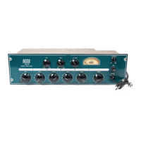
Figure 3.
Front View With Hinged Panel
Open
4
ELECTRICAL
5
120 Volt, 50/6 0 Hz Power Connections
5
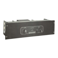
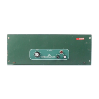
Figure 4. Rear View of 1593B Power
240 Volt, 50/6 0 Hz Power Connections
5
Amplifier
5
Battery Connections
6
Input Connections
6
Figure 5.
Converting to 240V ac, 50/ 60
Output Connections
7
Hz Operation
6
Speaker Matchi ng
7
Speaker Power Distribution
7
Figure 6.
Socket Wiring for Transfor mer-
OPERATION
7
Isolated Input Using 15095A
Line Transformer
6
CONTROLS AND INDIC ATORS
7
HIGHPASS Fl L TER
7
Table I.
Terminals and Applications of
SERVICE
7
INPUT Terminal Board 6
ACCESS
7
Table 11.
Speaker Outputs
7
ADJUSTMENT OF POWER DRIVER
BALANCE CONTROL
7
Figure 7.
Typical Solid-State Compon ent
ADJUSTMENT OF OUTPUT "Q"
BALANCE CONT RO LS
8
Configurations 9
ASSEMBLY REPLACE MENTS
8
Fuses
8
Pilot Lamp
8
Figure 8.
Component Locations Inside
Main Chassis
10
Power Driver PCB
8
RECOMMENDED SERV ICE TECHNIQUES
8
Figure 9.
Component Locations on Rear
Transistor Orientation
8
of Chassis
10
Replacing Power Transistors
9
Testing Transistors
9
Replacing PCB Components
9
Figure 10.
Schematic ( 2D356-7), 1593B
Power Amp lifier
11
Repairing Fractured or Damaged PCB
Conductor
9
Figure 11.
Component Locations ( 2C364-4),
PARTS LIST
13
Power Driver PCB Assembly
12
MAIN CHASSIS
13
POWER DRIVER PCB ASSEMBLY
14
-2-