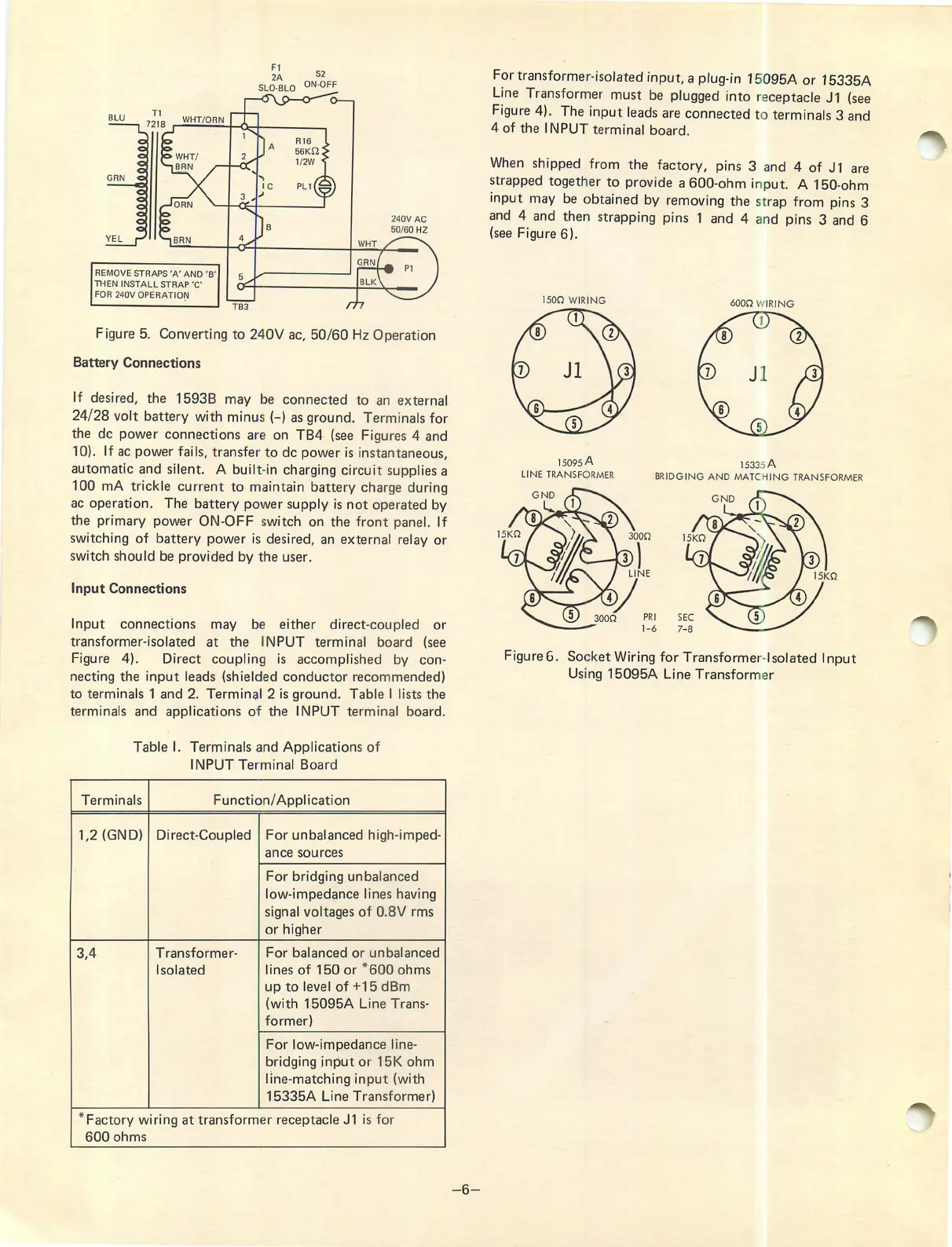
REMOVE STR APS 'A' AN D 'B'
THEN INSTALL STRAP 'C'
FOR 240V OPERATI ON
S2
ON-OFF
240V AC
50/60 HZ
Figure 5. Converti ng to 240V ac, 50/60 Hz Operat ion
Batt ery Connections
If desired, the 1593 B may be connected to an ext ernal
24/ 28 volt battery wi th minu s (-) as ground . Termin als for
the de power connections are on TB4 (see Figures 4 and
10). If ac powe r fails, transfer to de power is instantaneous,
automatic and silent. A buil t-in charging circuit supplies a
100 mA trickle curre nt to maintain batte ry charge during
ac operation. The battery power supply is not operated by
the primary power ON-OFF switch on the fr ont panel. If
switching of battery power is desired, an exte rnal relay or
switch should be prov ided by the user.
Input Connectio ns
Input connections may be either di rect-coupled or
transformer -isolated at the INPUT termin al board (see
Figure 4). Direct couplin g is accompli shed by con-
necting the input leads (shielded conducto r recommended)
to terminals 1 and 2. Termin ,;1I 2 is ground . Tabl e I lists the
terminals and applica t ions of the INPUT ter minal board.
Table I. Terminals and Applications of
INPUT Terminal Board
Terminals
Functi on/ Application
1,2 (GND)
Direct -Coupled
For unbalanced high-imped-
ance sources
For bridging unbalanced
low -impedance lines having
signal vol tages of 0.8V rms
or higher
3,4 Transformer-
For balanced or unbalanced
Isolated lines of 150 or * 600 ohms
up to level of +15 dBm
(with 15095A Lin e Trans-
fo rmer)
For low -impedanc e line-
bridging inpu t or 15K ohm
line-matching inp ut (with
15335A Line Transfor mer)
* Factory wiring at tr ansform er receptac le J1 is for
600 ohms
-6 -
For transforme r-isolated input, a plug-in 15095A or 15335A
Line Transfor mer must be plugged into receptacle J 1 (see
Figure 4). The input leads are connected to terminals 3 and
4 of the INPUT terminal board .
When shipped from the factory, pins 3 and 4 of J1 are
strapped togeth er to prov ide a 600-ohm input . A 150-ohm
input may be obtained by removing the st rap from pins 3
and 4 and then strapp ing pins 1 and 4 and pins 3 and 6
(see Figure 6).
1500 WIRING
15095 A
LINE TRANSFORMER
6000 WIRING
Jl
15335 A
BRIDGING AND MATCHING TRANSFORMER
Figure6 . Socket Wiring for Transforme r-Isolated Input
Using 15095A Line Transform er